Disclaimer
: These articles and procedures are examples of how and what can be done. These all assume the use of proper tools and the M535i SIG and I take no reponsiblity for any incorrect information posted on this page. If you are not comfortable in undertaking any automotive repair, take your car to a qualified BMW mechanic. Otherwise use this information at your own risk. Like the copyright says any duplication of this information with out the explicit permission of the M535i Special Interest Group & Registry is prohibited. If you run into any specific problems please email me through the link at the bottom of the page and I will try to assist you as best I can. If you have suggestions for improvements or corrections to procedures or other relative information please email them to me through the link at the bottom of the page.As for a fire bottle, the fire bottle mounts to the front of the driver's seat. To see exactly where please look at the interior picture on this page. Supposedly they are NLA, but I think you can still get them in Europe. The part numbers are. 72 60 1 887 447, which is the bracket to hold it to the front of the seat, 72 60 1 945 556, this bolts to the bracket to hold the fire extinguisher, and 72 60 1 945 969 which is the extinguisher. These parts are for the sports seats only, but will a little modification they fit perfectly on the couch seats and also work with the power couch seats.
Written by Rob Anderson '00Installing a rear spoiler looks easy, but is easy to mess up. What you want to do is drill once, and then install. You really don't want to have to make the holes oval. What I did was I took a large sheet of paper, enough to span the whole width of the car. Then fit is to the underside of the spoiler and punched the studs through the paper. Then cut out the indent for the roundel. After doing this, I looked a car that had the rear spoiler on, measured the distance from the top of the roundel to the bottom of the rear spoiler, where it sits over the top of the roundel. Once I had this measured I was then able to lightly stick the paper to the car. To put it in the proper place you use the measurement that I described earlier. Once it is positioned use the holes in the paper to act as a guide to where to drill.
The other way to do it is less precise, but if you have done it a couple of times it is easier and faster. What you do is paint the bottom of the studs in a color other than that of your car's. Once this is done, position the spoiler over the trunk lid and then slowly lower onto the studs. When the studs contact the paint they will leave a little dab of paint. You then drill on the different color dab.
I would suggest drilling from the ouside in, so that you don't have to sand down any burs. Make sure to prime and paint the new holes and try to use some super duty double sided adheasive so the spoiler is also stuck to the trunk and there is less chance of water getting into the car. I personnally would suggest the first method just because it is harder to screw up. The second method is easily screwed up if never done before.
Written by Rob Anderson '00This can be done without removing the sunroof or anything else for that matter. The front seal can be worked on with the sunroof about 80% open. There is room because the sunroof is actually not rectangular, and as it slides back some clearance opens up on the sides. The rear seal can be worked on with the sunroof tilted up. The general procedure is to remove both old seals by pushing straight down. First install the front seal, and make sure it is centered. You'll have to fashion a tool for seating the side portions (where there isn't much room to work) out of a bent coat hangar. Then tilt the sunroof and install the rear piece, starting from one end. The other end will be a bit long and need to be trimmed. Get the length perfect as the seal has metal molded into the rubber, so if you cut too short your new seal can't be stretched at all and is garbage. The whole job is about the same PITA factor as a windshield lock strip replacement, it'll take less than an hour. The parts are 51 12 1 870 086 (front) and 51 12 1 920 052 (rear). The pair cost me $58 from Maximillian. This made a noticeable wind noise improvement for me.
Written by Eric Rayl '00I've read that 535's and many other BMWs either came with a drivers door lock heater, or an interior light delay, but not both. In my case the door lock heater was non-functional because the electrical contact was broken off the control unit in the door. I believe this is a common failure. What the interior light delay does is keep the interior lights on for about 8 seconds after you shut the door, so you can find the ignition switch with your key.
I wanted the interior light delay, so I bought the "switch" for it, (61 31 1 375 197, $22.50 from Maximillian) and installed it. The "switch" is nothing more than a contact that grounds a brown wire with a green stripe when the door handle is pulled up. My car, and I assume all 535's already had the relay with the interior light time delay circuit in it under the dash. This switch is a plug in replacement for the door lock heater control module, so just plug it in and viola, interior light delay. The only other installation tip is that it's easiest to route the wiring if the rear window guide channel is removed, and only one screw holds it in.
Written by Eric Rayl '00First you will need quite a few butt crimp end connectors. You will also need the proper Euro plugs to plug on the back of the lights. Now this is what wiring you need to do.
Disconnect the battery.First, you need to locate pin number 85 in the low beam relay. Once locating this, mark it and remove the relay. Mark the exact plug it is. Then open the fuse box. Be careful as you don't want to pull any of the wires too hard. Then locate the other side of pin 85 on the low beam relay. You will see that it is a loop. What you need to do is find the one wire that runs between pin 85 and the high beam relay. This wire needs to be cut at the high beam relay. You want to cut it as close to the connector on the back of the high beam relay as possible without damaging the other wire coming out of the connector on the high beam relay. Now with this cut, strip it, and put a butt end connector on it. Then you will want to run a new piece of wire through the lower rubber grommet. After running this wire through the grommet, attach it to the other end of the butt end connector. Tape everything up, and close up the fuse box. Now with the wire on the outside of the fuse box, you want to run that to a ground. I run it to the main ground on the fender.
Now time for the lights. Remove the old lights. Now you will see 2 connectors that look like U s. The one on the high beam has 2 wires in it. One is a ground(brown) and the other is the power(white/blue or white/purple) from the relay. The power has 2 wires coming out of the connector. The one that runs to the low beam you want to cut. MAKE SURE YOU CUT THE RIGHT ONE! You can test by pulling on the wire on the low beam side and see which wire moves. That is the one you want to cut. Now, once that is cut, you want to pull it through to the low beam side. This will give you some extra wire that you will need later. Once you have done this for the high beam, then it comes to wiring the low beam. The ground(brown), a low beam power wire and you will have another wire which is loose. That would be the old high beam which you now are going to make into the street light. This is done by removing the side marker light in the bumper. You will see that it has 2 wires going into the connector. What I did was spliced in this wire into the power lead to the side marker light. This will turn on the street lights in the head light at the same time you put on the parking lights. And as for the third and final wire, that is the low beam wire. This does not need to be modified and connects directly into the plug or to the back of the light. Once this is done, then insert the Euro lights, and you will need to then wire the caps to the backs of the lights. Make sure that all of your connections are the same. For example you have the ground to the ground and the power to the power for the correct bulbs.
What this accomplishes is that when you turn on the high beams, the high beam lights come on, the low beams stay on, instead of switching filaments, and the fog lights stay on. This is the way the Euro cars work.
Written by Rob Anderson '01Well the way I have it wired up, which is the Euro way. What happens is that when you put on the parking lights the 4w bulbs turn on. Then if you flash the brights, only the center lights(high beams) turn on. Now, you put the switch in the second position and you will find that the low beam will turn on and the 4w will stay on which is how it works in the Euro cars. Now, if you put on the brights, the low beam and the high beam are both on, but the filament used in the low beam is the same all the time. You only use one filament in the low beam. In the US wiring, both filaments are used in the low beam so when you turn on the high beam, the low low beam filament turns off and the high low beam filament turns on. You have to eliminate this to have them wired correctly. By the way, the fog lights will also remain on when you have the brights on. So basically if you have the low beam on then you have filament number 1 in the low beam on and the fog lights. Now you put on the high beams. In the Euro wiring, filament number 1 remains on and so do the fogs and then the high beam turns on.
Written by Rob Anderson '01What you need to do is either get a new one(recommended) or a used one. Then to install it, all you need to do is remove the steering wheel, then unscrew the 4 screws that hold on the steering cover. With the wheel and the lower cover removed, you should be able to see the 2 screws that hold the stalk and switch to the column. Remove the 2 screws and pull out(you might want to remove the upper cover to prevent scratching or breaking it). Then once you have it out, there is a plug that you need to unplug on the bottom of the steering column. You should be able to get at it without removing the kick panel, but to make it easier, remove the kick panel. Unplug it, then plug in the new one, bolt everything back in and you are done. It should only take you about 1/2 hour to do.
Written by Rob Anderson '01The first question is, have you read the owner's manual on how to use it. I am not trying to be obnoxious, but many people email me saying they have CC problems, yet don't know how it works. Now when you set go to set the CC will the system take the gas pedal off your foot? If so then you know that the throttle control unit works. You also know that the relay is partially working and that the switch is partially working. So if this happens then I look elsewhere. The first place to look is at the clutch pedal. There is a sensor on the clutch pedal that will shut off the CC if the pedal is depressed. Make sure this is working correctly. Then I would check to make sure you are getting power to the CC system. There is a power accessory bus under the driver's side kick panel. This is located on the left of the pedal assembly on the fire wall. It has numerous plug ports on it and depending on what accessories you have some will have plugs in others won't. If you see a plug that is not plugged in right around this bus that is not blue then it has fallen out. It will only go back into one spot so plug it back in. If this is not the problem, then I would say make sure the switch works properly. That is that if you have it in the center(rest position), it is not giving the signal to shut off the CC. This can be done with some continuity tests on the switch itself. If the switch turns out OK, then I would look at the relay. This can only be checked by changing it with another one. If this doesn't fix it then you are having a problem getting the speed signal from the instrument cluster to the CC system. If it turns out to be that, email me I will guide you through checking it.
Written by Rob Anderson '01This procedure took me 2.5 hours, first time doing it, and including numerous breaks (even a 20 minute dinner break). You do NOT need to drain the coolant. Only if you really can get your hand around the back of the intake manifold and around the back hose, then you just need to remove that one hose (it goes from the heater valve to the engine head or block).
Again, this is a much better way to replace the starter, and you don't need a machined thin wall socket. You CANNOT get a socket in to those bolts to begin with so DON'T even try.
Another little trick is to use the BMW wrench in the trunk tool kit. Supposedly it fits perfectly allowing you to get the starter off. BMW thinks of everything!
I'd like to thank Erick Baumeister who first told me of this little trick.You can install the US ECU in a Euro car. The only problem is if you have the Euro car with the 218 bhp motor, there is no O2 sensor. The US ECU takes readings from the O2 sensor in the exhaust to calculate how rich or lean the car is running at that time and then modifies how much fuel is entering the motor. The Euro ECU does not have this input. Therefore when you stick the US ECU into a Euro car, there will be no O2 sensor reading. The car will run on the US ECU without an O2 sensor, but the chip in the US ECU is programmed so that if the O2 sensor fails or is disconnected, or not connected at all, the car will run at full rich. This will foul your plugs and also give you poor emissions.
From the info that I have on Euro ECUs I find that the chip in them is pretty much maxed out as it is. I would suggest leaving the Euro ECU in the car and if you want to play with your mixture for better fuel economy, use the adjuster screw on the underside of the airflow meter to change the air fuel ratio. With this said, be careful of how much you play with it as the car may take poorly to the adjustments. It is better left to a professional or an experienced home mechanic. I have performed this procedure on my father's Euro M635csi and I found that the car prefers to run a little on the rich side. Most BMWs do, so I would not mess with it too much.
Written by Rob Anderson '00Ok, I think I need to explain to you what is important in the numbers on the ECUs. ALL ECUs that work with a motronic 1.0 635csi with a cat. are part number 0 261 200 059. They also have the number of 1 705 619.9 Now, this does not tell you anything. The reason why is that I have had now 2 ECUs with these numbers, but one had a 24 pin chip and the other has a 28 pin chip. The number that really matters is in a small circle on the right side of the purple label. If that has a 78 inside it then it is a 24 pin ECU. If it has a 965 in the circle then it is a 28 pin ECU. Now, the part numbers on the chips mean absolutely nothing. This is because BMW supersedes its part number so often, especially in the '80s that it is almost impossible to trace.
Written by Rob Anderson '01In the head, on top of the cam, there is an oil sprayer bar that directs oil to lubricate the cam and rockers. The oil spray bar bolts are hollow bolts through which oil passes through, into the oil sprayer bar. Now, these bolts tend to come loose in time from vibration. This can happen in as little as 20k miles, or as long as 150k miles, there is really no "set" mileage that this happens.
BMW has issued a new bolt to fix this problem. Really, what it is is the same bolt with a tad of locktite on the threads. But it is a new partnumber and the old bolt (with no blue locktite) and the new bolt are differentiated by a round circle engraved in the head of the new bolt. The part number for these bolts is 11 42 1 738 621.
Any good (i.e. knowledgable) BMW mechanic should know about this problem on M30s. And whenever you get a valve adjustment (which should be every 15k miles or 1-2 years), the mechanic should check the torque on those bolts. So long as you do that, you should have no problem. Even with the "old" bolts.
BTW, a valve adjustment on these cars should run around $100, give or take. This includes a new valve cover gasket. That is the only repair that I'd take, and have taken, my car to a mechanic to. You really need to get a "feel" to adjust the valves on M30s. It's an art in itself. But if you do do it yourself, you have to do with the engine stone COLD, because otherwise you won't do a good job. (Leave it sitting overnight). Oh, and you will also need a method to turn the engine (remote starter, big socket and wrench to turn crankshaft rotating nut, etc).
Written by Chris Graff '01The best way I have found to get a lot of NORMALLY ASPIRATED power out of an M30 is to do the following.
First you start off with an M30 b35 motor. Lets take for example the E34 535i. First dismantle it because a lot of internal work needs to be done. First lets concentrate on the block. I don't like stroking, but I love boring. So Custom JE forged pistons that raise the compression to 10:1 and have a 94 mm bore. Top End Performance can get them with Total Seal Rings which are far better than BMW. Now, radius the con rods as that will increase strength. Of course I suggest using new con rods and bearings. Use the stock 86 mm stroke crank, but have it cross drilled and rifle bored. This will increase low end oil pressure and also the life of your rod end bearings which is a good thing because you will be making a lot of power. Now, you start to assemble the bottom end. Pistons, rods, crank. Then you get to the oil pump. You need to use an E28 oil pump because without it, you will not be able to bolt on the E28 oil pan which is necessary to clear the subframe. Now you have the bottom end built. I suggest using a lightened flywheel also from Top End Performance. 15lbs is light enough and an M5 clutch should do you. Now that you have the bottom end together, it is time to work on the top end. Let me just say, that with the bore increase you will have a 3.58L motor. Also please don't forget it is important to use the E28 motor mounting arms so you can bolt the block to the subframe. I also suggest using 2 of the left side motor mounts from an M5 as they are stronger than the stock units.
As for the head, use a stock E34 head to start. Skim it to make sure it is flat and then take to the machine shop. Port and polish it, and also do a three angle valve job. Now depending on what cam you are running you might want larger valves but I think that the 47 mm intake and 38 mm exhaust are just fine. New guides, etc. Then radius the rockers(new) which will give them added strength for the extra duration and lift of the cam. Now I suggest using Metric Mechanic progressive rate valve springs and also their head oiling upgrade kit. You can use titanium retainers if you like, but I don't think you will need to. You can use pretty much any cam you want, but I suggest not going below a 278. Now back to the machine work, you will also need to have the combustion camber diameters enlarged in the head to work with the larger piston bore. I forget what this technique is called, but it is very easily done. An adjustable cam gear will let you advance and retard your cam for better performance or better economy.
For the head gasket, I believe you can use the early big six, with the 93.5mm bore gasket, but I would suggest getting a custom one with a solid metal ring in it so that you have less chance of blowing the gasket. I don't have a source on where to get one, but I have heard that lots of Drag Racers who run high boost get them.
On to the intake and exhaust. For the intake I would suggest starting with the E34 M30 b35 intake. Then I would port and polish it and then port match it to the head. This will give you the maximum flow possible. As for the exhaust, custom headers are in order that have 1 5/8" primaries that go into 2 2" collectors. I would run an E28 M5 exhaust. You should also be able to use the E24 M30 b35 intake bracket to support the intake to the block. The E34 M30 b35 bracket will not work.
Fuel system and engine management. Use either custom engine management or Motronic 1.3 out of the late '88 and '89 E24, along with the engine harness. This is because the motronic unit will then mount in the same place as the one currently in the car. I would then suggest a dyno day and a custom burnt chip. As for fuel system, I suggest running Mustang 24 lbs hr injectors at either 3.0 bar or 2.5 bar depending on your fuel requirements. I would also suggest using a big bore throttle body because you will need as much air as possible. On this note, a Mass Air Flow Meter is in order as it will give the engine management more precise readings and also will be less of a restriction, and of course cone filter.
As for oiling system, I would try to run the E28 oil filter canister and housing because I am not sure that the E34 M5 canister and housing bolt on to the E34 M30 b35 block. I would never run this motor without an oil cooler.
Written by Rob Anderson '01Based in large part on our discussion about engine building, I'm very pleased w/ the results of my b34-b35 combo.
Running the older Motronic I produced 206 hp and 219 ft lbs with the new motor. The old stock (w/ JimC) motor, on the same dyno 18-20 months earlier was 156/164 as I recall.
Torque comes on around 3400 and lasts thru peak HP at 6200. Shifting at peak drops me into the torque band and all's well.
Dyno done late '02the M5 and M535i have oil coolers, even the Euro 535i has an oil cooler, so why doesn't mine? Well it does now. I spent a lot of time looking into putting in a oil cooler. The one main problem I ran into was the fact that no aftermarket housing would bolt onto the block. This means that the oil filter housing has to be replaced with one from one of the previously mentioned cars, and M635csi and M6 and Euro 635csi(post '82). These are not very easy to come by and are very expensive from BMW.
I was able to find a used housing off of an M5 and then started at a cooler. I orignially purchased a Euro 635csi cooler and lines. This cooler fit in to the car, but the lines did not come close to fitting. I then looked into replacing the lines with ones from a US M5, but I found that the design of the M5 cooler is different than that of the Euro 635csi. I then looked into getting a cooler from an M5, but those aren't easy to find. So I found that a 524td has the same oil cooler as an M5!! But the coller lines are not the same. I looked into what lines to use. I thought that I might be able to use a Euro 535i or M535i line, but since I have the big US bumpers, they won't fit.
I then looked into what car has US bumpers, and an oil cooler. The only car is the US M5. Then with a quick check of part numbers, I found that the US M5 has diffferent lines than any other 5 series. I also was able to find an M5 that I was able to look at and found that behind the airdam the US valance was still fully intact. This gave me the confidence to purchase the expensive M5 oil cooler lines and install the cooler. The installation was fairly simple, but required the removal of the aux. cooling fan, and the front grills. The lines were the first things to go into the car, and require the bending of a small tab from the lower valence down. Once the lines were in, I placed the oil cooler in the car. I had to make custom brackets to hold the cooler, but once that was done, everything bolted together. I made sure to put oil into the cooler before I bolted everything together so that I didn't have a lack of oil pressure when I started the car. Now the car has a cooler and I see lower oil and water temperatures.
Written by Rob Anderson '01
M30 Oil Pan Removal
The easiest way is to lift up the passenger side of the motor, off of the motor mount. I have the front of the car on ramps and then use a floor jack, raised up on wood under the oil pan, also using wood between the jack and the pan. Then, I lift the motor off of the passenger side mount by jacking up under the oil pan after the motor mount retaining bolts have been removed. Once I have gotten it up a good distance. I got mine so that the head was just touching the firewall. I then put a jack stand under the AC compressor bracket(make sure you put it under the side that does not need to be moved, or remove the part of the bracket that is in the way before starting the jacking). The I lower the motor onto this jack stand. Remember, it will take a little while for the motor to come off the mount because you are basically removing a lot of weight from the front of the car so the suspension will decompress. Once you have done this, then go about removing the oil pan bolts. Once you get all of them out, the pan will drop, but you won't be able to pull it out. You need to reach into the crack between the pan and the block and remove the oil pump from the block and most importantly the sprocket at the front. Once you have done this, the oil pump should drop into the pan. Then you should be able to remove it no problem and accomplish any work you need. To install it, it is the reverse of removal. Make sure you have the pump in the pan and put them up together, because they won't go in separately.
Written by Rob Anderson '01To remove the tank, remove the fuel lines from the filler plate underneath the access in the floor of the trunk. Also remove the electrical connectors from the fuel pump and level sender. Open up the fuel filler door in the side of the car, remove the filler cap, and pull out the rubber piece that surrounds the filler neck. Now you can see 3 small lines hose clamped to 3 small metal and fragile looking pipes which are part of the tank. These 3 lines are difficult to remove. If you are replacing your tank, you don't have to be gentle about pulling them off. I think I ended up cutting the line off of one particularly stubborn pipe because it looked like there was enough line left over to reattach to the new tank.
If you haven't run the car until it is almost out of gas, I highly recommend draining most of the gas out of the tank. There is a drain plug on the right front lower corner of the tank which uses a crush washer to seal. I think it took a 5mm allen wrench to remove the plug. Try to keep the drained gas out of the nice cars. Save it for the Oldsmobuick and the lawnmower
DO I NEED TO REMIND ANYONE OF THE DANGERS OF AN OPEN DRAIN PAN FULL OF GASOLINE? HOW ABOUT THE EXPLOSION HAZARD OF A CLOSED METAL CONTAINER FULL OF GAS VAPOR?
Before loosening any bolts, put your flor jack under the tank to keep it from ventilating your skull. I believe there are three bolts holding the tank off the ground. One bolt may be partially abscured by the exhaust so you may have to loosen or remove hangars to get to it. I had to move my exhaust a couple inches to drop the tank. You may also have to remove the right side swaybar bracket. There was a bent metal clip under the swaybar bolt in my car which was blocking the tank. Remove the bolts and lower the tank. Installation is the reverse! This would be a good time to replace all those dried out fuel lines in the back half of the car.
I had a decent tank from a garage kept 528e which happened to be sitting in my driveway. Upon tremoval of the 528e tanks, I found a litle surface corrosion but nothing that caused great concern. The Maximillian price of $220US for a new tank is very good so I suggest buying a new tank instead of throwing a rusty disaster-waiting-to-happen into your car.
Written by Ed Walters '00Here are the part numbers and what they are rated at.
Stock E28 535: 19.82 lbs/hr @ 43.5psi (3bar)
Stock Mustang: 19 lbs/hr @ 38psi
The increase in flow rate is proportional to the square root of the increase in pressure. To convert the mustang flow rate to flow rate at BMW pressure:
STOCK(Sorry don't know the part number) 19 * (43.5/38)^1/2 = 20.33lbs/hr approx. 2.6% increase.
M9593A302 24 lbs/hr @ 38psi so 25.68 lbs/hr at 43.5psi approx. 29.566% increase.
Now it all depends on how much power you are going to be making. My thought is that if you will be getting close to 260, so you will want an injector that can handle that amount of power at 85% duty cycle. Since the stock injectors can handle 240 on lets say 100% duty cycle. So, a 19 lbs/hr injector from a Mustang which would be a 20.33 in our car, you will be able to put out 3% more power at the same duty cycle. So you will be able to put out somewhere close to 247hp. Now lets go to the 24 lbs/hr injector which is 25.68 lbs/hr in our cars. That gives you a 29.566% increase which means that it can support 311 bhp. Now you only want to be running at about 85% of that so, at 85% duty cycle you will be able to support about 264hp. If you find that the car is running too rich, then you can always lower the fuel pressure which is very easy. You just use a 528e fuel pressure regulator, which is 2.5 bar.
Written by Rob Anderson '01Do you know how the system works? What it does is take the gas vapor from when the gas heats up or is poured into the tank and then condenses it and inserts it into the intake. This makes for a wet manifold as well as non-metered air entering the intake. This system was a complete after-thought from BMW and all true Euro cars don't have it. The reason why is because the US EPA wanted to prevent the gas vapors from escaping to the atmosphere. What really they are doing is creating a situation where you are getting extra air and fuel vapor into the combustion. As you will know, gas vapor does not combust as easily as liquid, and in fact is very hard to combust, and is therefore put through the cat and out the tail pipe. This increase the emissions of the car and also robs power because of the wet manifold condition and the increase in un-metered air going into the motor.
After completely understand how this system works and what it does to the operation of the motor, you will see that it has no benifit and in fact the claim you made of having your premium evaporting should happen because of the way the system works in the European cars where the expansion tank is vented to the atomsphere. What expansion tank does in European car is that it acts as a collector for the gas vapor and then once the gas vapor converts back to liquid, it flows back into the tank. This is also shown by the placement of the expansion tank in the car. The expansion tank is placed higher than the main tank and is also far away from a hot exhaust. This allows the gas vapors to cool and therefore condense back into a liquid and flow back into the tank. Thw only reason why there is a line to the outside of the car is that in cases when you are filling up the car, you are inputing more gas than air can come out. This therefore allows for the pressure in the tank to be released and so you are able to fully fill the tank. I have had this happen on a 7-series where I was filling it up and the pump stopped, but the tank was not full. This was caused by the charcoal canister system and the fact that it doesn't allow pressure to be released from the main tank quickly in situations like filling the car. Also, the possitioning of the line port on the expansion tank that runs to the charcoal canister is also at the top of the tank. If you know about chemistry, the gas vapor will settle to the bottom of the tank because of the fact that it is heavier than the normal air. Therefore, the normal air will go out of the expansion tank, and the fuel vapor will stay in. Now you are correct in saying that when you fill the car it will smell like gas for a little bit, but you are incorrect in saying that you want positive pressure in the gas tank. While positive pressure will allow for the tranfer pump to work easier, you will not be able to fill the car fully after driving. Also the charcoal canister system does not keep positive pressure in the tank. If you have ever looked at the canister and how it works, it is open to the air on the underside. This allows for the prevention of a build-up of pressure in the tank, but it doesn't work very well.
In closing, the charcoal canister system was an after-thought by BMW to abide by the EPA laws. Personally, after reviewing how the system and the problems that it cause, such as rough idle, incorrect mixture, poor emissions and difficulty in filling, I see now reason to keep the system on the car unless it is required by the emissions laws in your state.
Written by Rob Anderson '01This is my opinion from personal experience. I am sorry if I offend anyone. First, I have had Korman, UUC, and AutoSolutions. The Korman one was cool in the fact that I could adjust it, but that quickly went away as the shifter wore quickly. I then replaced it with the UUC Stage 2 (the Street Evo - there are 3 stages, from bottom to top is Street, Street EVO, and Competition EVO with ERK). I was much happier with it compaired to the Korman one, but found that it did not include all of the bushings to remove the slop on older linkages. These are the bushings found far forward in the shifter mechanism, near the tranny. You need to buy them separately, and if you don't know the PN's off hand, you need to find someone with a Parts CD to do the leg-work. I did like the spherical bearing in the mechanism, and I think that is a good idea. Unfortunately, the UUC shifter also wore out fairly quickly. It took me twice as long to wear it out as the Korman, but still, I needed to replace it.
The BMW shifter has a couple of points that make it wear. The first being that the shift rod, which holds the handle, is actually 2 pieces. This is the reason shifters wear out - because between the top portion of the shifter (where your shifter knob attaches to) and the bottom portion (where the pivot point and bearings are) is a rubber insulator (which you cannot really see unless you look at the shifter itself at certain angles). This is true for every shifter. It is there to reduce vibration up to your hand. The time it wears away is a function of quality of workmanship, tolerances, bushing design, and material. UUC uses a rubber bushing in there which is not sealed well, in my opinion, from the elements. It is done in a similar fashion to OE BMW. The AutoSolutions shifter is actually connected using Urethane and is sealed with silicon to prevent degredation by heat and other factors.
And this is why I then tried AutoSolutions - as I had seen a couple of people were starting to try them so I got myself one. The kit included every part you could ever think of to do the job. The build quality was also higher than the UUC because it uses different materials and a different assembly for the insulator between the top and bottom portions of the shifter. The only drawback that I found with the AutoSolutions shifter is it does not use the spherical bearings that the UUC ones use. As far as notchiness, the AutoSolution is perfect, not too notchy, but stiff enough to let you know you are in a gear. Like the UUC it keeps the shifter in the stock location, but reduces the throw. The throw is comprable to the UUC. I also prefer the way that AutoSolutions makes their shifters. They are custom made, while the UUC is similar to the OE BMW ones in that it looks like a modified BMW shifter.
Overall, I believe that the AutoSolutions shifter is worth the extra money because of the higher quality of the insulator between the two shiter pieces. The UUC is a good value, and it's spherical bearing on the lower pivot is a very good idea (on the EVO series), but it is a shifter for the value conscious. Also the cup removal tool that you are given with the UUC kit does not work. I ended up taking a screwdriver and knocking out the cup and then inserting the new one. The tool was completely useless, unless the shifter was out of the car.
In an ideal world, I'd use the AutoSolutions short shifter, with the UUC sealed cartridge bearing.
I hope this helps you with your decision.The best way I have found is to manually bleed the system. You will need a friend to help you. You are under the car with the bleeder screw, a tube and a bottle along with the correct wrench to loosen and tighten the bleeder screw. I suggest a box ended wrench. Put the box ended wrench on the bleeder screw. Then put on the tube. Put the other end of the tube in the bottle. Now, what you do is with the clutch pedal up, this is your friend, you loosen the screw. Then your friend pushes the pedal down and holds it to the floor. Then you tighten the screw and they pull the pedal up. Then you repeat until you have gotten quite a bit of fluid through. I usually go for at least an inch in the bottom of a Snapple bottle. Once you have done this, you will find that the pedal still is really soft. What I then do is pump the pedal. You pump it until it gets hard. Once hard, then drive the car. If you like it, then leave it. If you don't repeat the process. It usually takes me 1/2 to an hour to properly bleed a clutch manually, but remember I have done it a lot of times.
Written by Rob Anderson '01First lets start out by saying that the car has two separate gear ratios, that can be changed independently of one another: the tranny ratios and the diff ratios.
For the tranny side of the equation, there are three different trannies used in the late E24s. First we will concentrate on the two overdrive units. These are the Getrag 260 and 265. The 265 has a removable bell housing and is used in only the '85 model year cars. BMW upgraded to the 260 which has a one piece case, but shares the internals. The 260 parts are stronger and use the following ratios.
First - 3.83These are the ratios for all US spec late E24s save M6. Lets look at the third tranny. This is a close ratio, Getrag 262. This tranny has completely different ratios than the overdrive trannies. This tranny has a removable bell housing and often a dogleg first gear. This is a weaker design than the overdrive tranny but has its benefits in the ratios.
First - 3.72Notice the close ratio tranny put 5 ratios in place of the wide ratios 4 and does away with overdrive. In order for BMW to keep the same high speed capability and derivability the differential ratio is different between cars fitted with the close ratio and the overdrive gearbox.
All US spec late 635csi 's' and 633csi came with a 3.46 diff ratio. This diff ratio is always coupled with the overdrive tranny, worldwide. If the car was equipped with a close ratio tranny than the diff ratio was changed to 3.07. This was in order to keep the same speed capability but also maximize acceleration. If a 3.25 diff is fitted to a close ratio equipped car it is like driving an overdrive car without fifth gear. Swapping in a 3.73 into an overdrive equipped car is like having the close ratio/3.07 combination on the highway. The benefit of the close ratio tranny is that acceleration in the upper gears is like having a low differential ratio, but first and second gear do not become stump pullers.
Written by Rob Anderson '00I personally have a 3.73 in my car with the 260 trans. I find that it is great for cruising around 75-80, but above that you get the car on cam. Then it has less derivability. What you need to figure out is what is the cruising speed you will be doing. Lets say on average you will be doing 100 mph. You will have a .81 5th gear. Now I will go through the step by step calculations of how to calculate rpm in a given gear with a given tire diameter, and a given diff ratio.
First we find the circumfrence with respect to miles for the tire size you have. So, the stock car came with 200/60 390s. So here is how you calculate the circumfrence.
Aspect ratio, in this case 60 and divide it by 100, you get .6.The taller you gear the car, aka the lower the number, the slower off the line the car will be. There will be no loss of top speed if you use a 3.73 because our cars can only hit top speed in 4th gear with a 3.25. Now if you put in a 3.73 you will hit a higher top speed but in fifth gear. The reason why it is higher is because you are multiplying rear axle torque by a greater factor therefore pushing the car through the air with greater force. Off the line you will get better acceleration the lower the gear, aka the higher the number. But you will have less fuel economy up top. The best fuel economy occurs right before the car comes on cam. In a stock 535i it comes on cam at approx. 3250. If you gear the car so that you highest cruising speed is at 3250 than you will get them most fuel economy. You do not want to have you top speed occur there though.
Written by Rob Anderson '00You are going to need to get the proper allen sockets that fit into the large hex bolts in the diff. The reason why I say allen sockets is because I have bent many an allen wrench doing this job.
Jack the car up on the diff and place jackstands under the rear subframe. Then lower the car onto the jackstands. Then use the allen socket to break loose the filler bolt. Make sure to do this first because if you can't get it out you don't have a diff without fluid. Once you have this out, remove the drain plug and let the fluid drain. My suggestion would be to not jack up the car very hi so that you can get the most oil out of the car. Once you have emptied it all out, then lower the car all the way back down and let the rest drain.
Jack up just the left rear. Place the drain plug back in and tighten it. Using a long tube, insert one end into the diff and then have a friend pour the fluid into the other end of the tube. Read your capacities section of the owner's manual and it will tell you how much should go in. Another way to do this is fill it until it starts to come out of the filler opening. This has been set at the correct hieght so that it will overflow when you start putting in too much fluid. Then tighten up the filler plug and lower the car down and you are done.
I recommend using Redline oil in the diff and also if you have a limited slip I would also suggest using GM limited slip additive. This works with the limited slip clutches to help prolong the life of the clutches.
Written by Rob Anderson '00First jack up the rear of the car so that both rear wheels are off the ground. Now I usually place jack stands under the rear subframe but if you do not want to place them under the subframe that is fine, place them where you feel comfortable. Now remove the jack(s) and let the rear of the car sit on the jack stands.
Remove the 6 bolts that hold the half shafts to the diff. This is most easily accomplished by having a hex head socket that you can use. With these removed, the half shafts should be easily removed from the diff. By the way, don't be afraid to rotate the half shafts to make it easier to get at these bolts, in fact I suggest it. To hold the half shafts still, put the parking brake on and also put the car in gear. It is not good to have the half shafts hang so I suggest after removing them from the diff to either place blocks of wood under them or to hang them from the body by string.
Next unbolt the driveshaft. To hold the driveshaft still to be able to remove the nuts, put the car in gear and that will hold the driveshaft still. With all 4 bolts removed, you will need to try to push the driveshaft forward in the car. If you don't you run the risk of separating the driveshaft when you pull the diff out of the car. This is a really bad thing to do.
Now that you have the driveshaft and half shafts disconnected, then unbolt the diff from the subframe. Remember to place a floor jack under the diff before you remove all the bolts because remember it will drop on you and it weighs a lot. With all the bolts removed, lower the diff on the jack and roll out from under the car.
When doing this job I suggest replacing your diff mount and also to rotate your half shafts. This is done by unbolting the half shaft where it mounts to the hub and bolting the end of the the shaft that was once bolted to the diff to the hub. This gives greater life to the half shafts.
This step only applies to late E24s
Depending on what diff you are using, you might need to chance the rear cover which is very easily done by unbolting the cover on both the new and old diff and just swapping them. Don't forget to use a new seal, and I suggest using a gasket sealer with the new gasket because if you use a synthetic, most likely it will leak, and this will prevent the leakage. To change the output flanges, use the butt of a hammer handle to pop the old and new shaft out. With them removed, push the new ones in. You will notice that they only going in so far easily. You will need to push them in harder until they are all the way in. this can be done by some hand force or you can use a soft mallet to knock them in.
Now place your new diff in the car and bolt it to the subframe and diff mount. With these bolted in, I also suggest using loctite or another suitable thread locker to prevent these bolts from vibrating loose. Then bolt up the driveshaft and tighten the four nuts that hold the driveshaft to the diff. Then reinstall the half shafts, and remember the spacers that have to go on. I would also suggest that you use thread locker on all of the bolts that hold the half shafts on. I have seen it a couple of times where even at the correct tightening torque, these bolts back themselves out. Tighten the the half shaft bolts to the correct tightening torque which is something like 43 ft lb. Then take off the parking brake and also take the car out of gear and rotate the rear wheels. If you notice anything wobbling then investigate, if not, then you are done. Take the jack stands out and drive the car and make sure there is no vibration of clunking.
Written by Rob Anderson '01I would first look at your diff mount. If it is bad, it will cause the diff to sag which will contribute to poor rear suspension geometry as well as putting excess strain on the universal joint in the driveshaft. Then I would want to check to see if the half shaft ends are still round. They generally oblong which can cause a low speed vibration. Then I would move to the guibo. Check to see if that is good. If you see cracks it must be replaced. Then look at tranny mounts. If they are broken that will cause the tranny to move around under hard load causing a vibration. Also check to make sure the center bearing is preloaded correctly. If it is, it should be deformed slightly towards the front of the car. Also make sure the motor mounts are still good. With all of this checked and/or replaced, if you still have the vibration then most likely you will need a new driveshaft.
Written by Rob Anderson '01Jack the car up on the front subframe and put the jackstands under the frame rails. You have to then remove the front wheels, making sure to loosen the lug nuts before taking the car off the ground. Once that has been done, using the open end of the 17mm combination wrench, find the 2 notches in the ball joint, on the ball joint side. See Diagram
Do this at both ends of the link and installation is the reverse of removal. Make sure to have the nuts nice and tight and then lower the car down and torque the lug nuts.
Written by Rob Anderson '00First and least likely to cause steering slop is that the tie rods, center link and idler arm in the steering are exceedingly shot. I doubt this or the car would shimmy badly, but you may not feel that because of the second and or third problem.
Second would be that the steering box itself is worn. Many times the power steering fluid isn't replace or is replaced with the wrong stuff. Our cars use ATF(Automatic Transmission Fluid) in the power steering. I have seen more than once a shop put in Power Steering Fluid in the power steering system. This is not good and causes the box and other parts to wear. A temp. fix would be to tighten the adjustment screw on the top of the box and that should eliminate some of the play. If you have a huge amount of play, this could be caused by the box. With this much play I doubt you would be able to feel if the steering arms where shimmying. The way to check to see how much play your box really has is to have a friend turn the steering wheel, only the amount of the play and see if the input to the box is moving. If so, is the output, or pitman arm moving. If not there is your problem.
Third cause. This is also to do with the box and comes in now. The reason why I tell you to check to see if the input to the steering box is moving is because the steering column is actually 2 pieces. These are held together using a large nut, and that nut actually loosens over time. All you would have to do is tighten it up.
Fourth and final. This is the worst and this should be check immediately. This is a grave situation which faces our cars. The mount that holds the steering box to the sub frame actually breaks!!! Yes I said breaks!! It slowly goes until it lets go all together and you loose all steering. BMW had a little known recall/suggested fix that the put out in the early '90s. There is one large long bolt that holds in the steering box. This bolt was inherently weak on the E28 and other cars. They have since upgraded the strength and have superseded the part number. If this is the problem on your car you will need to take it to an experienced mechanic who will be able to weld the brackets back on to the front subframe and reinforce them.
Written by Rob Anderson '00It depends on the year of the E24. The E24 was upgraded to a collapsable steering column in '86. This steering column has a different steering wheel. There are 2 reasons why it is different. The first is that on the old style steering columns the steering lock was in the column, with the collapsable column the lock is actually at the top of the steering column and locks into a hub on the back of the wheel. The second difference is the number of splines in the wheel and on the steering column. If I remember correctly there are more splines on the collapsable steering column wheel than on the non. So even if you could get the wheel to get close to mating, it would not slide on because of the different number of splines, so it all boils down to what year E28 wheel are you talking about.
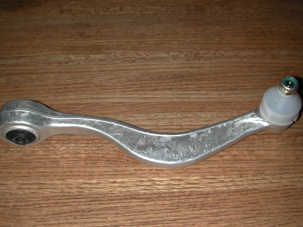
Written by Rob Anderson '00Aluminum Lower Control Arms from any and all E34s bolt into our cars. These aluminum control arms generally have few advantages over the steel ones. The first is that they weigh less, and the second is that they are slightly stronger. This is a must for those who spend lots of time on track but from my personal experience, they don't last much longer than steel control arms but cost quite a bit more. The decision is up to you, but my 5 has steel arms. Here is a picture of the aluminum arm.
A clunking in the front suspension, can be a couple of things. First I would think that it would be the upper strut bearings. The way to check this is to find a bump on a secluded road and have a friend drive the car very slowly over the bump with the hood open and your hand on the upper strut bearing. If you feel the clunk in your hand then it is most likely either the upper strut bearing or the shock. The next thing to look at is whether the bearing is deforming or the strut is moving and the bearing is not. If the rubber of the bearing is deforming then you have a seized strut. If the strut moves and the bearing does not deform then I would suggest replacing the bearing. The clunking can also be caused by very badly worn ball joints, but I doubt that if you have no shimmy problems.
Written by Rob Anderson '01A couple of months ago I contacted you about putting Koni's on my E24. The folks at TCKline were great in working with me on this and although there was somewhat of a wait for the parts, as of today my '87 is now wearing Koni Sports (rebound-adjustable) front and rear. It has completely transformed the ride characteristics of the car. It no longer feels like a 15 year old car with 205,000 miles. In fact, my wrench (Bill Rudtner at Rudtners Racing) went for a test ride after the installation and came out with a big grin! This from a guy who's the Technical Advisor to both the NY CCA and PCA chapters!.
Despite having previously done other suspension maintenance and mods including new control arms, bushings, tie rods, 750i front brake upgrade, ditching the TRX's for 850i rims with Dunlop SP5000 225/50/ZR16's, none of these changes really "clicked" until now. Finally, the benefits of all that work is paying off! I know you and I are in the minority when it comes to advocating Kon's, but heck, we just need to convert people one at a time!
Thanks for your advice and encouragement.
Written by Roger Katz '02You must jack the car up by the differential and then place the jackstands under the rear subframe. Safety first. Then use the 13mm wrenches to remove the bolt that holds the link to the U shaped clamp on the trailing arm. Then pull the link off of the swaybar. To install the new link I would suggest using a mixture of soap and water and rubbing it in the rubber bushing. This makes it easier to push on to the swaybar. Then bolt the bottom of the link back into the U shaped clamp and torque to 16-18 ft pounds.
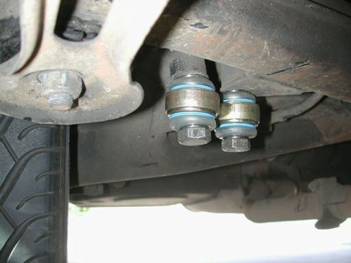
Written by Rob Anderson '00The rear toe link or rear pitman arms, are a source of common problems in handling of the E24. This is because these units are designed to control the amount toe change while the suspension moves. When these bushings wear out, it can cause a clunking noise in the rear of the car over bumps and can also cause these cars to be a handful in the wet. They are very simple to change and can be purchased through any BMW dealer or Maxamillian. The replacement of these bushings can usually be done without removing the wheel or jacking up the car. If you have clunking, or feel that your car has bad wet weather driving characteristics than check these bushings. Basically, if the dust boots are broken they need to be replaced. Here is a picture.
If you measured the width of the wheel, for example an 8 inch wheel. You then find the mid-point of that which would be 4 inches from the edge. The the hub on the wheel, where the wheel bolts to the car, is 4 inches from both edges of the wheel you have a 0 offset. This means that you have 4 inches off of the hub, or towards the outside of the car, and 4 inches inside the hub, or towards the inside of the car.
If we look at American cars for a second, as the offset number increases, the further off the hub the wheel sits, on an AMERICAN CAR. BMWs are the opposite. We have what is considered to be negative offset. This is because as you increase the offset number value on a BMW, the further inside the hub the wheel sits. That is why our offset is measured in ET. That takes into account the negative.
Now for an example. We will use my Hartge wheels. In the rear I run 16x8.5 wheels. The offset is ET25. This means that the wheel sits 25mm further inside the hub than an offset of ET0. So, that means that instead of having 4.25 inches on either side of the hub, I have approx. 5.25 inches inside the hub and 3.25 outside the hub. Now on the front I run 16x7.5 wheels. The offset is ET15. This means that the wheels sits 15mm further insider the hub than an offset of ET0. So, instead of having 3.75 inches on either side of the wheel, I have approx. 4.25 inches inside the hub and 3.25 outside the hub. Now you ask how does this effect the fitment on the car.
Well on a BMW there is generally more room on the inside of the hub than on the outside. The fender well is a finite width, unless you modify it, and the hub sits a specific distance from the outside of the fender well and the inside. The higher offset number you have, the further towards the center of the car the wheel sits, so therefore the less chance of having the tire rub on the outside fender. But for example I tried putting my 16x8.5 wheels on the front of my car. The problem I found was that I cannot bolt the wheel to the hub because the strut tube hits the inside of the tire. So on the front there is only so much distance between the hub and the strut tube. This is what generally governs front offset. In the rear though, the clearance on the fender is what governs offset. Depending on the width of the wheel and the offset, you may or may not have to use a spacer. What a spacer does is change the offset number to what you want. So if I had a wheel with an ET35 I could use a 10mm spacer to get the wheel back to an ET25. But if you get a wheel with too low an ET number than you may have to mill the hub of the wheel down to get the correct offset.
Written by Rob Anderson '00OK you say you have ET11, so your wheels stick pretty far off the hubs huh? Do you have a picture of the car with those wheels on it? Here is what I say, what tires are you running now? BMW used a 16x7 with an ET of 20, so you should have nothing to worry about with getting the 225s to clear the strut tubes. But you might have to severely roll the fender lips front and rear. ET11 means that the wheels are sitting quite a ways off the hubs. For example I am running 8.5s in the rear with an offset of ET25. They required rolling when I lowered the car. Therefore we will do some math.
I currently have 8.5s with an ET25 that means that my wheels are 215.9mm wide. Now to find the center line, or ET0 I divide by 2. 107.95 Now if I have an ET25 that means that the wheel sits 25mm further in towards the center of the car therefore making it so that I have 82.95mm from the hub to the outside of the rim. And I have 132.95 from the hub to the inside of the wheel. Since I had to roll my fender lips with the 8.5s we will do the math for your wheels and see if they will fit.
You say you have 7s with an offset of ET11. Now your wheel is 177.8mm wide. Therefore we divide by 2 to find ET0. 88.9mm Now you say you have ET11 so that means that you will have 99.9mm inside the hub, towards the center of the car. And you will have 77.9mm outside the hub. Ok so your wheel is actually further away from the fender lip than mine.
Now we will figure out if you can fit the 225s in the rear. I run 245s, which are exactly 29.1mm wider than my wheels. This means that they stick out on either side of my wheels by that much. So we divide by 2. 14.55 This is how much my rear tire sticks off of my rim on the outside. So if you measure the distance from the hub to the edge of my tire you will find that it is 97.5mm. Now with that width I had to roll the fender lips.
This is what you will have. Your 225s will stick 47.2mm outside of your wheels. Therefore on the outside they will stick out 23.6mm. So your distance from the hub to the outside of the tire is 101.5mm. Therefore you will have to roll your fender lips more than I have to. What this means is that your rear tires will sit 4mm further towards the outside of the car than mine. This may not seem a lot, but it will require some serious fender lip modification, especially on a lowered car. As for the fronts we will use my front Hartge's to compare to.
I have 7.5s on the front of my car with an ET15. This means that I have 110.25mm inside the front hubs and 80.25mm outside the front hubs. Now you are using the same wheels front and rear so I will copy and paste the previous calculations.
You say you have 7s with an offset of ET11. Now your wheel is 177.8mm wide. Therefore we divide by 2 to find ET0. 88.9mm Now you say you have ET11 so that means that you will have 99.9mm inside the hub, towards the center of the car. And you will have 77.9mm outside the hub. Ok once again your wheel is actually further away from the fender lip than mine.
Now we do the tire calculation again and we find that I run 225s on the front of my car. So the tire sticks off the rim a total of 34.5mm So the measurement from the hub to the outside of the tire is 97.5mm. Now I have not had to modify anything on the front of my car but I am also running 1.25 degrees of negative camber.
As per the previous calculations, you would have a distance from the hub to the outside of the tire of 101.5mm. Therefore again your wheels will sit futher off the hubs and would require more rolling or may require rolling in the front. As for strut tube clearance, you are fine, but when you start talking about clearing the body panels, I don't think it will be very easy.
Written by Rob Anderson '00Remove the driver's side kick panel. Place car on slight incline, not very steep or you will not have a car. Steep enough for the car to be able to roll on its own. You then locate the top of the brake pedal. You will see an aluminum U shaped bracket with a pin through it attached to the brake pedal. If you follow this U shaped bracket, you will come to a lock nut and then a threaded rod which goes into the brake bomb. Once you have located that, loosen the lock nut. Then place the car on the hill. MAKE SURE YOU LEAVE THE CAR RUNNING! Otherwise you will never be able to adjust it properly. OK here is the tricky part, where if you are not careful you can loose your car, so I suggest having a friend in the passenger seat manning the parking brake. You leave the driver's door open and while outside the car on your knees, you actuate the brake pedal. You use a pair of pliers or you hand to rotate the threaded rod in or out of the U shaped bracket. By doing this, you are adjusting where the brakes pick up. To test, you put you hand on the brake and tell your friend to take of the parking brake. You then slowly release until you feel the car start to move and then you put it back on. I would not suggest getting it too tight because like I found once, there was a very small air bubble in my brake lines and the brakes seized on, which was not fun. I leave 5mm-1cm before anything happens so that I will never run into this problem again. After getting it to the proper positioning, tighten up the lock nut and driver the car. See if you like it, and if you don't work at it some more. Once you get it to where you like it, button everything up and don't worry about it anymore. Very easy to do and makes the car a lot more fun to drive because you get much better feel through the pedal I found.
Written by Rob Anderson '00After upgrading the brakes on an E24, the best way to get the feel through the pedal you have always wanted is with stainless steel brake lines. I would personally use Earl's lines for an E24 M6. The front lines are slightly longer than the 635csi, and so that will take up the slack for the different caliper input. If you are still running the 635csi calipers and better pads, the 635csi lines work great. They are the best quality I have found and you should have no problems putting them on. Many people put E34 brakes on their cars and ask the question of whether they should use E34 lines or E24 lines, since the part numbers are different. My answer to this is, "I say use the E24 M6 lines." The reason why the E34 lines are different is because the pick-up points on the body are in a different location, therefore requiring different length lines.
Written by Rob Anderson '00What has happened is that the ABS system has detected a fault in the reading of the vehicle speed. This can be caused for a variety of reasons, but these are the most common.
First, you want to clean the ABS toothed wheel. If the ABS sensor cannot get the pulses from the wheel, then the system will register a fault in the speed readings. These wheels can have dirt lodged in the teeth, chipped teeth, rust, all sorts of things. If you have a chipped tooth on the wheel, you will have to replace it. More often than not, it's just rust or dirt.
Second, you want to clean the ABS sensor itself. It is simple enough to remove the sensor (a couple screws and pull out), but be careful because they are plastic and can break if you're not careful pulling them out.
If cleaning the wheel and sensors doesn't work. Replace the sensors. Or try to find a working set to swap to see if you can pin point the bad sensor. They are pretty fragile, so be careful pulling them in and out.
The reason why the ABS light doesn't come on immediately when you start the car is because ABS works only above 5 mph or so. Only after you go that speed it then attempts to read the signal. Unfortunately the signal is bad and the system then disables the ABS, and the light goes on.
An example of a failure method is having the sensor not read the teeth. In effect it is not sending out a pulse. The other wheels are. The computer reads the pulses as the speed of the wheels (the faster the pulses, the faster the speed), so when the computer reads the speed for the 3 wheels, and no speed for the other (because there are no pulses), it registers an error. You're not applying the brakes (so it's not like a wheel is locking up under braking which would cause the pulses to stop because the wheel isn't moving), so the computer realizes there is a problem with the sensors and disables the system. If it wouldn't do this, when you'd brake, the ABS would activate, and the brake on the wheel with the bad sensor would not activate because it reads it as if the wheel were stationary. That means only one side of the car at that end would brake causing you to veer off. Not a good thing.
Written by Chris Graff '00Here are a list of stages of braking upgrades. The amount of benifit you recieve from the upgrade is mainly dependant on the pads and rotors you use.
Stage 1: E32 frontsAs our car age, various things go wrong that you would not expect to have happen on a new car. Some of these problems most DIYers don't think twice about attempting, but there are some things that most people shy away from. For example, the average DIYer will have no problem doing a brake job, but when they find out that they have a stuck caliper, many just think that their only option is to purchase a remanufactured unit through a dealer or Maxamillian. Well, this is not the case, BMW and Maxamillian sell what are known as caliper rebuild kits. These kits come with all of the necessary rubber O-rings to rebuild a caliper. Now lets say you have a stuck caliper on your 635csi, and you have decided that you want to attempt to rebuild your own caliper(Which is not something I suggest to an inexperieced DIYer).
First, you need to remove the outer dust boot. Once this is removed you must remove the piston out of the caliper. To do this you can use one of three ways. The first one is to just push on the brake pedal until it pops out. This is accomplished by having the rest of the brakes on the car and working correctly, then you unbolt the questionable caliper from the trailing arm or strut tube and then you remove the pads. Once this has been done, then you have a friend push on the brakes. You will see the piston start to move. Now you will want to have a catch can under the caliper because as soon as you get the piston out the brake fluid that was in the reservoir and in the brake line will come out. Be careful to catch the piston when it pops out because you don't want to damage it. This is an easy way of removing the piston, but you will find that you can only do one caliper at a time and then you have to bleed the system before you can do a second one. It is also difficult to rebuild the caliper with it still attached to the brake line. So the second and third way involve removing the caliper completely from the car, this is also the preferred way to rebuild a multi-piston caliper like those lovely E24 M6 calipers that you just bought to put on your car. The second way to remove the pistons is to used compressed air. In the port that the brake line screws into, you pump compressed air into the caliper and this will push out the piston. This is the preferred way to do this step. Now, some of us who have rebuilt quite a few calipers have found that the fluid, and the compressed air won't loosen the piston. Well don't worry, there is one more way of removing the piston. This involves using a vise grip and a vise. First you clamp the vise grip to the piston with as much force as you can. Now remember, you only want to clamp it to the unmachined surface. This is the area that is in direct contact with the pad. You will notice that it has a small diameter then the rest of the piston. Once you clamp the vise grip on, then you place the handle of the vise grip into the vise and tighten it down. Now you need to grab the caliper with both hands and try to rotate the piston in the bore. This is made easier by plenty of releasing fluid. Once you have gotten it to rotate in the bore then you need to carefully pull the piston out of the caliper by pulling and rotating at the same time. The reason why you do both at the same time is because you want to make sure that you don't cock the piston in the bore. If you cock the piston you will find that you can damage the caliper bore. Now, people with the M6 multi-piston calipers will be asking, how do I get the vise grip on the piston. Well what you need to do is unbolt the two halves of the caliper. There are four bolts that hold the caliper together. Once you have removed these four bolts put them in a safe place because they are no longer available from BMW. You will also notice that there are two spacers, and four small O-rings. Non of these parts are available from BMW anymore, so it is important not to lose them. I suggest that once you have the small O-rings out that you soak them in NEW brake fluid. WHEN REBUILDING CALIPERS ONLY USE NEW BRAKE FLUID!
Now that you have the piston out, you open your rebuild kit. There is a larger rubber O-ring in the kit. This O-ring is actually placed in a groove in the caliper bore. You need to remove the old O-ring. Then it is time to clean out the caliper. This is easily done with compressed air, but can also be accomplished by plenty of brake parts cleaner. Once you have cleaned out the caliper you need to inspect the bores. If you see any rust in the bore, you will need to clean it out. This is done by carefully and I mean carefully using some emery cloth on the rust spot. Now that you have gotten rid of the rust spot, you need to inspect the bore for any scoring. If there is some slight scoring you can probably smooth it out with the emery cloth, if there is deep scoring you will need a new caliper. Once you have cleaned and inspected the bore you will need to coat it thoroughly with brake fluid. Then soak the new rubber O-ring in brake fluid and install. Make sure that the seal is not twisted in any way. Now you need to clean any rust off the piston and also inspect it for scoring marks. Once you have cleaned it and inspect it, you can cover it in brake fluid and carefully reinstall it in the bore. You must be very careful doing this because you need to make sure that you don't cock the piston. But unlike removing the piston you cannot rotate and install the piston at the same time. You need to push the piston in by hand. You will know if the piston is cocked because it will become very very difficult to install. Now remember you will need to get the piston by the rubber O-ring so don't mistake getting the piston by the O-ring with it being cocked. Now that you have the piston back in you need to put on the new dust boot. Once you have that on, the piston caliper is back together. And for those with the M5 calipers, you will need to bolt back together the two halves of the caliper. Make sure to clean everything and wet it down with break fluid. Also make sure you reinstall all of the small rubber O-rings and make sure not to pinch them. Once everything is back together, I suggest for your floating caliper to use high temp. wheel bearing grease on the guide bolts. This will ensure smooth operation of the caliper. Bolt the caliper back onto the car and bleed the brakes.
Now you have successfully rebuilt your caliper and probably saved yourself at least $100 for each caliper.
*The E24 M6 caliper is just like any other multi-piston BMW caliper and so the techniques can be applied to all multi-piston BMW caliper.
Written by Rob Anderson '01BMW started back in the late '60s and early '70s denoting their bodies with an E and then a number. They also have denoted their motors by an M and then a number, or in special cases an S and then a number.
Here is how the E worksAs for the motors BMW started with the original 4 cylider and has gone from there.
M10 - Four cylinder found in 2002 and 320iM motors go by a different designation. They use S.
S14 - E30 M3 motor based on M10.Autocrosses are cheap, fun way to push you (and maybe your car) to its limits and learn how to drive. Contact your local BMW CCA chapter (most have websites with the schedule up anyways), and see when the autocross season starts. Autocrossing, for those who don't know, is a form of racing/timed event held in parking lots. The organizers set-up a course that twists and turns, usually with a few chicanes or "gates", and usually with a slalom area as well. Each "lap" lasts between 30 seconds and change, all the way to 1 minute and 30 seconds. Each driver gets between 3 and 6 runs per session, usually. And there are 2 sessions (morning/afternoon). And you usually don't end up going faster than 60 mph. Most corners are done in second gear around 20-40 mph. Gates or chicanes you *might* use 1st, but more often than not you shift once, on acceleration from the start, into second, and leave it there for the lap.
Autocrosses are a great way to learn how to drive well at the limit. They're inexpensive (you can even borrow helmets from the organizers usually), and very fun. The more you do, the more you learn how to handle oversteer/understeer and other driving situations. You learn how to drive the car, and not let it drive you. Not only that, but since it is relatively low speed, if you do spin out or get in trouble, all you end up hitting are cones. There is no grass, walls, trees, etc., that you have to worry about like at a driver's school. (Interesting experience: One funny thing, I ended up locking my wheels going into a very sharp corner at an autocross once. About 35 to 10 or 15 mph braking. The interesting thing was that I was at the limit of braking (without engaging ABS), and I guess that at that slow(er) speed the wheels all locked up at the same time or in a similar fashion in that the ABS didn't engage...oh well. Hit a cone...2 second penalty...that's about it, didn't happen again afterwards. Hey, it was only my second lap.)
Anyway, my point is that many of you out there know your cars well and enjoy to drive them on a regular basis on the street. But, you have an entirely different character to your car that you do not know about. It's the fact that these cars are made to handle extreme driving conditions. Once you've done a few autocrosses or driver's schools in a BMW, then you'll realize that you have a helluva piece of engineering. You will be AMAZED that anyone can build a car that can not only be reliable and handle everyday chores, but hold its own at driving events.
Remember though, that you have a 3200 lb-ish car, with relatively antiquated suspension (versus newer BMWs), so don't expect the big 5-er to be as fast as...say 3 series or M3s out of the box. This is why the more nutty enthusiasts here want to modify our cars... hehe... But, also remember that at an autocross, a good driver is worth at least 5%, if not more, of the lap time. I know for certain, that if Ed Walters drove my car, he will pull 2-3 seconds on me, guaranteed, within a couple laps.
In any case, this will definitely get most of your "enthusiastic driving" out of your systems so you don't endanger the general public (just j/king), and make you a better driver. I can attest to the fact that Autocross experience has saved me at least 2 times in winter weather driving.
And let me just add, PLEASE FLAG! Autocrosses can only be run if there are people willing to work. Just think that is a way to get a T-shirt tan and be really close to the action. Most flaggers only have to reset the cones that others knocked over.
Written by Chris Graff '01