Technical Articles and Step by Step Procedures
Disclaimer
: These articles and procedures are examples of how and what can be done. These all assume the use of proper tools and the M535i SIG and I take no reponsiblity for any incorrect information posted on this page. If you are not comfortable in undertaking any automotive repair, take your car to a qualified BMW mechanic. Otherwise use this information at your own risk. Like the copyright says any duplication of this information with out the explicit permission of the M535i Special Interest Group & Registry is prohibited. If you run into any specific problems please email me through the link at the bottom of the page and I will try to assist you as best I can. If you have suggestions for improvements or corrections to procedures or other relative information please email them to me through the link at the bottom of the page.I got mine from England. It cost me $50 and I believe this is the part number. You will need the bracket number 72 60 1 900 099 and some hardware associated with it 07 11 9 907 957, and 07 12 9 925 735. The medkit number is 82 12 9 406 691. It is listed as NLA, but I got a brand new one from England. It is not an M5 only part, in fact, many Euro cars came with it, but I believe it was standard on the M5.
Written by Rob Anderson '00There is a new Part number for the med kits: 52 20 1 859 303. It is about 30 EUR in europe, check with your local US supplier for more exact pricing info.
Chris Graff '02As for a fire bottle, the fire bottle mounts to the front of the driver's seat. To see exactly where please look at the interior picture on this page. Supposedly they are NLA, but I think you can still get them in Europe. The part numbers are. 72 60 1 887 447, which is the bracket to hold it to the front of the seat, 72 60 1 945 556, this bolts to the bracket to hold the fire extinguisher, and 72 60 1 945 969 which is the extinguisher. These parts are for the sports seats only, but will a little modification they fit perfectly on the couch seats and also work with the power couch seats.
Written by Rob Anderson '00New fire extinguishers are available, PN 72 60 0 000 335. They are 1kg, and require 72 60 1 906 501 Mouting parts set for fire ext. for sports seats. PN 556 from above is for use with the NLA (969 from above) 1.3kg fire ext.
Chris Graff '02Installing a rear spoiler looks easy, but is easy to mess up. What you want to do is drill once, and then install. You really don't want to have to make the holes oval. What I did was I took a large sheet of paper, enough to span the whole width of the car. Then fit is to the underside of the spoiler and punched the studs through the paper. Then cut out the indent for the roundel. After doing this, I looked a car that had the rear spoiler on, measured the distance from the top of the roundel to the bottom of the rear spoiler, where it sits over the top of the roundel. Once I had this measured I was then able to lightly stick the paper to the car. To put it in the proper place you use the measurement that I described earlier. Once it is positioned use the holes in the paper to act as a guide to where to drill.
The other way to do it is less precise, but if you have done it a couple of times it is easier and faster. What you do is paint the bottom of the studs in a color other than that of your car's. Once this is done, position the spoiler over the trunk lid and then slowly lower onto the studs. When the studs contact the paint they will leave a little dab of paint. You then drill on the different color dab.
I would suggest drilling from the ouside in, so that you don't have to sand down any burs. Make sure to prime and paint the new holes and try to use some super duty double sided adheasive so he spoiler is also stuck to the trunk and there is less chance of water getting into the car. I personnally would suggest the first method just because it is harder to screw up. The second method is easily screwed up if never done before.
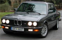
Written by Rob Anderson '00This conversion came about with the longing for Euro bumpers, yet not wanting to have to have a new valence put on the front of the car. This conversion can be done to any US E28 that has not had its valence seriously damaged or modified for any reason. And other than cutting up the valance is reverse-able back to USA form any time.
First the US bumper must be removed before any work can start. This is accomplised by first unplugging the turn signals that are inset into the bumper. Then using an 8mm socket, remove the six mounting bolts, three on each side, that hold the bumper shocks onto the frame rails. With these removed, carefully pull the bumper straight forward away from the car.
Now the bellows must be removed. First take out the side marker lights. You will see, once you remove the white plastic housing that holds the bulb, a body screw. This is the only reason you have to remove the side marker lights. Now remove the 8mm body screws that hold the bellows to the front upper apron. The front upper apron is the panel that holds the kidney grills and the light grills. Also don't forget to remove the screw that is located behind the side marker light and the screw that is located inside the fender, and screws into the bellows from inside the fender.
With the bellows now removed we can start modifying the valence for the turn signals and fog lights. The valance has the cut-outs were the lights mount already indented. So you can easily match up were the lights are supposed to fit in. Here is where you really need to be careful. If you cut too much off you can't stick it back on.
You now have to do some measuring. Take your turn signal and you will see a gasket around the outside of it. This gasket is suppost to fit snuggly into the valence. What needs to be done is you must measure to figure out were your mounting tabs need to be located. The reason why you must measure is because you don't want to just cut out the valence for the lights. You want to cut it out so that you leave mounting tabs for the lights. All you then have to do is drill a single hole and use a body clip to hold the light to the valence.
You'll have to match the mounting screws on the lights to the valance. Please remember to include all three mounting brackets/tabs for the turn signals. The fog lights mount differently.
Now I used a marker and marked what had to be cut and what needed to be saved. Then I used a 13mm drill bit and drilled four holes in the edges of the pieces that were not needed. This gave me access to be able to put the blade of the riciprocating saw into them and cut out the small panels. With the panels cut out, I bent the tabs that were left over back and away to
test fit the lights. Where it wouldn't fit I would use a file or an angle grinder to get rid of the excess metal.
Once the light fit properly, I bent the mounting tabs in order to match the screw holes in the lights, and marked them for drilling. Do not mark them prior to cutting the valence because you will have to bend them into the car and then up (like in an "L" shape, please see accompanying photos). I made sure to make the center brackets as large as possible.
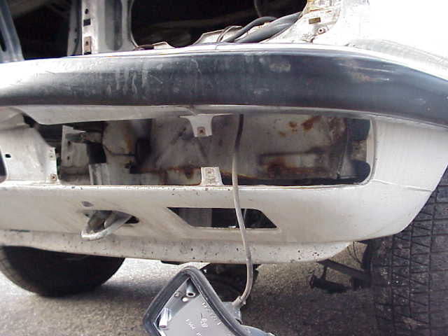
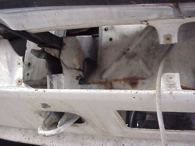
Now on to the all important fog light opening. Many people say you have to cut the whole frame rail back, but that is not true. All you need to do is use the riciprocating saw to cut horizontally through the frame rail at the same hieght as the top of the opening in the valence. Then you need to cut the frame rail vertically. You do this only enough so that you can fit the fog light in. What you're going to cut is actually the corner of the frame rail extension flange. You will cut out one of the mounting holes for the USA bumper shock, but you have the other 2 if you want to reinstall. Now here is a difficult part, if you think the rest is easy, you need to get a cutting wheel on the dremel, and you have to cut the frame rail far enough back so that the frame rail does not hit the back of the fog light. Once you have done this, this should remove the lower outside part of the frame rail as previously stated. This is all you have to remove. DO NOT REMOVE ANY MORE THAN NECASSARY!
Now that the lights are able to fit in, you now what to completely assemble the bumper. Tighten everything up and try to insert it inside the frame rail extentions (where the bumper shocks used to mount to). You will find that you can't. The reason being is that you will need to cut the circle in the lower inside, to be a square corner. This is easily done with the riciprocating saw. This then allows for the bumper brackets to sit level. Insert the bumper in the frame rail and you will see that it sits far to
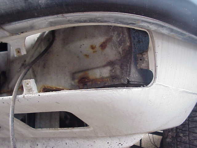
low. The reason is that you have to bend the euro bumper mounting brackets. This is in order to mount them and for height. If you look into your frame rail extention, you will see that the bottom of the frame rail extension slopes down towards the back of the car. Your bumper mount needs to be more or less flush along this bottom side. The reason we're doing this, is because the euro bumper mounting lips on the frame rail were cut in order to fit the USA bumper shocks. Then there was a frame rail extension welded on the frame rail ends to which the bumper shock mounts.
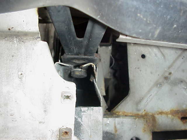
In the picture you see the small lip that the brackets lay on, and through which the bolt is put on. The USA cars will be different in that the euro brackets will be BENT and mount on the bottom part of the USA frame rail extension. In order to mount the bumpers Euro style, you will need to take off the USA frame rail extensions and weld BACK on the bumper mounting lip inside the frame rail, which is what the euro cars have.
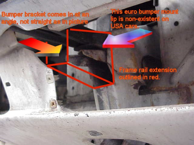
Now you have to hard mount the bumper to the frame rail exension, so you have to bend the bracket so it sits flat against the bottom of the frame rail extension. Now that you have done that you should be able to bolt up the outside bolts that hold the bumper to the fender, using the holes in the fender that used to hold the belows on. If they do not line up, then you have not gotten the bumper situated correctly. Keep bending the mounting bracket until you can get the holes lined up. Now you have to mark the hole that must be drilled in the bottom of the frame rail extension. This hole is for the bolt that holds the bracket to the frame rail extension. You wonder how to drill this hole now. It is a pain. You need to get yourself a foot long drill bit. YES A FOOT LONG! Now this trick only works on the cars with the valences with the plastic towing eye covers. These are the later cars, but there is probably a way to do it on the early cars too. Open the plastic towing eye cover. Then you will need to jack up the front of the car. With the front of the car in the air, you can insert the drill bit. To get a good clean hole, I ran my drill bit up through the towing eye. This lined up correctly and I drilled the holes. With the holes drilled, test fit everything.
Now that you are test fitting everything, you will see that we haven't drilled the hole to mount the fog light adjuster bracket (the inside mounting bracket of the fog light). Do this now. You will only be able to drill the lower hole, but that is just fine, you do not need the upper screw to mount the bracket. Drill the lower hole and if everything bolts up, remove it all. This is the point at which I removed the little plastic plugs that hold the belows to the upper apron. These are a pain to get out. I suggest cutting them out. You cannot get to the backs of them so you have pull them out which is a pain.
Now that you have that stuff out, run the turn signal wires back into the valence. The reason why I did not say this before is that you could very easily cut the wires with the saw if they are inside the valence. Then prime the cut surfaces and any rust you spot. I use POR 15 paint as my primer. In the visable places, after it dries, I coat those with body color paint. Even though the body color paint may not match exactly, the texture of the valence covers that fact.
Everything is now painted and the paint is dry. This is when we wire up the turn signals and fog lights. First we do the turn signals. I had turn signals that had a dual filament bulb (like USA cars). This let me have the manditory marker light and turn signal all in one. You will also have to stick a reflector on the inside of the lens on the side so that you meet DOT regulations and pass inspection. Once you have done this, then you can wire the lights.
I cut off the connector that is used power the side marker light. This has 2 wires in it. One ground and one power. The power wire I run up to my Euro lights to run the city light. If you do not have the Euro lights, I would suggest leaving the connector on the wiring harness and taping over the end and tucking it in the valence. As for the 3 pin connect that powers the turn signal/marker light that is mounted in the bumper, cut off the connector on the US harness. At this point the brown ground wire goes to the brown ground wire. Then you will have to experiement with which wire powers the turn signal and which powers the marker light. You want it so that the marker light powers the low filament and the turn signal powers the high filament in the bulb. This will give you what you need.
Now that you have the indicator lights wired up, you can wire up the fogs. This is how I did it. You get the Euro 5 fog lights, they are different than any others, they come with wiring attached. Depend on the condition of your wiring, you might want to splice the new wiring into your car's harness, but the connector that is on the fog light is not found on the US wiring harness. So you will have to cut off the connector and hard wire it into the harness. What I did was remove the wiring that came with the fog light, took the rubber grommit off of that wiring. Then I removed the rubber grommit from the wiring on the car and pushed on the new grommit. I then installed the wiring from the car into the fog light. This saved on wiring and also makes for a cleaner install. With this wired up, I bolted in my lights, using body clips and sheet metal screws. The sheet metal screws screw into the body clips not the valence or any other body part.
With all of that bolted in, I bolted on the bumper for the last time and you are done. I looks really good, but for the work I would hope so. It should take you anywhere from two to five days to do depending on how confident you are with your bodyworking skills.
Written by Rob Anderson '01This can be done without removing the sunroof or anything else for that matter. The front seal can be worked on with the sunroof about 80% open. There is room because the sunroof is actually not rectangular, and as it slides back some clearance opens up on the sides. The rear seal can be worked on with the sunroof tilted up. The general procedure is to remove both old seals by pushing straight down. First install the front seal, and make sure it is centered. You'll have to fashion a tool for seating the side portions (where there isn't much room to work) out of a bent coat hangar. Then tilt the sunroof and install the rear piece, starting from one end. The other end will be a bit long and need to be trimmed. Get the length perfect as the seal has metal molded into the rubber, so if you cut too short your new seal can't be stretched at all and is garbage. The whole job is about the same PITA factor as a windshield lock strip replacement, it'll take less than an hour. The parts are 51 12 1 870 086 (front) and 51 12 1 920 052 (rear). The pair cost me $58 from Maximillian. This made a noticeable wind noise improvement for me.
Written by Eric Rayl '00There is a way to adjust the hood latch by adjusting the pin's length. If you look at the pin, there is a nut that locks it against the plate that bolts to the hood. First you must loosen this nut. Then using a flat tip screw driver, you unscrew the pin and then when you get it to where you want it, tighten the nut back down. Then test the hood and if it looks good and locks correctly then your done. If it needs more adjustment, then repeat until you get it where you want it.
Written by Rob Anderson '01I've read that 535's either came with a drivers door lock heater, or an interior light delay, but not both. In my case the door lock heater was non-functional because the electrical contact was broken off the control unit in the door. I believe this is a common failure. What the interior light delay does is keep the interior lights on for about 8 seconds after you shut the door, so you can find the ignition switch with your key.
I wanted the interior light delay, so I bought the "switch" for it, (61 31 1 375 197, $22.50 from Maximillian) and installed it. The "switch" is nothing more than a contact that grounds a brown wire with a green stripe when the door handle is pulled up. My car, and I assume all 535's already had the relay with the interior light time delay circuit in it under the dash. This switch is a plug in replacement for the door lock heater control module, so just plug it in and viola, interior light delay. The only other installation tip is that it's easiest to route the wiring if the rear window guide channel is removed, and only one screw holds it in.
Written by Eric Rayl '00Note that the left side motor has 3 output leads (red, black, brown), and the right has 4 output leads (red, black, brown, and blue). The red is a 12V (+) momentary on; the black is a 12V (+) constant on; the brown is ground; and the blue is a output signal to the washer pump. To test each motor, connect a 12V(+) to the black lead, and ground to the brown lead. With another wire, touch the red 12V(+) lead for 2-3 seconds only. The motors should cycle on for about 30 seconds, then shut off.
The installation instructions should still be available for the E28. However, there is a copy of the E30 versions available here:
Headlight Cleaning System With Intensive Wash Installation Instructions (1.3 mg .pdf file)
Headlight Cleaning System Installation Instructions (2 mg .pdf file)
First you will need quite a few butt crimp end connectors. You will also need the proper Euro plugs to plug on the back of the lights. Now this is what wiring you need to do.
Disconnect the battery.First, you need to locate pin number 85 in the low beam relay. Once locating this, mark it and remove the relay. Mark the exact plug it is. Then open the fuse box. Be careful as you don't want to pull any of the wires too hard. Then locate the other side of pin 85 on the low beam relay. You will see that it is a loop. What you need to do is find the one wire that runs between pin 85 and the high beam relay. This wire needs to be cut at the high beam relay. You want to cut it as close to the connector on the back of the high beam relay as possible without damaging the other wire coming out of the connector on the high beam relay. Now with this cut, strip it, and put a butt end connector on it. Then you will want to run a new piece of wire through the lower rubber grommet. After running this wire through the grommet, attach it to the other end of the butt end connector. Tape everything up, and close up the fuse box. Now with the wire on the outside of the fuse box, you want to run that to a ground. I run it to the main ground on the fender.
Now time for the lights. Remove the old lights. Now you will see 2 connectors that look like U s. The one on the high beam has 2 wires in it. One is a ground(brown) and the other is the power(white/blue or white/purple) from the relay. The power has 2 wires coming out of the connector. The one that runs to the low beam you want to cut. MAKE SURE YOU CUT THE RIGHT ONE! You can test by pulling on the wire on the low beam side and see which wire moves. That is the one you want to cut. Now, once that is cut, you want to pull it through to the low beam side. This will give you some extra wire that you will need later. From what I remember the Euro connectors on the back of the lights are different than the US ones. You can do this next step 1 of 2 ways. First you want to remove the female spade connector from the plastic. DAMAGE THE PLASTIC, NOT THE CONNECTOR. Once you have the connectors removed, you can either just plug them on the back of the light, or you can insert them into the Euro connectors. If you have a used Euro harness, when removing the female spade connectors, damage the metal when remove them from the EURO harness. This will preserve the plastic which you will need when you insert the spades on your wiring harness. Once you have done this for the high beam, then it comes to wiring the low beam. The ground(brown), a low beam power wire and you will have another wire which is loose. That would be the old high beam which you now are going to make into the street light. This is done by removing the side marker light in the bumper. You will see that it has 2 wires going into the connector. What I did was spliced in this wire into the power lead to the side marker light. This will turn on the street lights in the head light at the same time you put on the parking lights. And as for the third and final wire, that is the low beam wire. This does not need to be modified and connects directly into the plug or to the back of the light. Once this is done, then insert the Euro lights, and you will need to then wire the caps to the backs of the lights. Make sure that all of your connections are the same. For example you have the ground to the ground and the power to the power for the correct bulbs. There are 3 prongs on the back of the H4 bulb, one of these is ground, one is low filament and the other is high. You can place the low beam lead on either one of the filaments and then change them to see which you like better.
What this accomplishes is that when you turn on the high beams, the high beam lights come on, the low beams stay on, instead of switching filaments, and the fog lights stay on. This is the way the Euro cars work.
Written by Rob Anderson '01Well the way I have it wired up, which is the Euro way. Even though the H4 has 2 filaments, the Euro wiring only uses one. So what happens is that when you put on the parking lights the 4w bulbs turn on. Then if you flash the brights, only the center lights(high beams) turn on. Now, you put the switch in the second position and you will find that the low beam will turn on and the 4w will stay on which is how it works in the Euro cars. Now, if you put on the brights, the low beam and the high beam are both on, but the filament used in the low beam is the same all the time. You only use one filament in the low beam. In the US wiring, both filaments are used in the low beam so when you turn on the high beam, the low low beam filament turns off and the high low beam filament turns on. You have to eliminate this to have them wired correctly. By the way, the fog lights will also remain on when you have the brights on. So basically if you have the low beam on then you have filament number 1 in the low beam on and the fog lights. Now you put on the high beams. In the Euro wiring, filament number 1 remains on and so do the fogs and then the high beam turns on.
Written by Rob Anderson '01What you need to do is either get a new one(recommended) or a used one. Then to install it, all you need to do is remove the steering wheel, then unscrew the 4 screws that hold on the steering cover. With the wheel and the lower cover removed, you should be able to see the 2 screws that hold the stalk and switch to the column. Remove the 2 screws and pull out(you might want to remove the upper cover to prevent scratching or breaking it). Then once you have it out, there is a plug that you need to unplug on the bottom of the steering column. You should be able to get at it without removing the kick panel, but to make it easier, remove the kick panel. Unplug it, then plug in the new one, bolt everything back in and you are done. It should only take you about 1/2 hour to do.
Written by Rob Anderson '01The first question is, have you read the owner's manual on how to use it. I am not trying to be obnoxious, but many people email me saying they have CC problems, yet don't know how it works. Now when you set go to set the CC will the system take the gas pedal off your foot? If so then you know that the throttle control unit works. You also know that the relay is partially working and that the switch is partially working. So if this happens then I look elsewhere. The first place to look is at the clutch pedal. There is a sensor on the clutch pedal that will shut off the CC if the pedal is depressed. Make sure this is working correctly. Then I would check to make sure you are getting power to the CC system. There is a power accessory bus under the driver's side kick panel. This is located on the left of the pedal assembly on the fire wall. It has numerous plug ports on it and depending on what accessories you have some will have plugs in others won't. If you see a plug that is not plugged in right around this bus that is not blue then it has fallen out. It will only go back into one spot so plug it back in. If this is not the problem, then I would say make sure the switch works properly. That is that if you have it in the center(rest position), it is not giving the signal to shut off the CC. This can be done with some continuity tests on the switch itself. If the switch turns out OK, then I would look at the relay. This can only be checked by changing it with another one. If this doesn't fix it then you are having a problem getting the speed signal from the instrument cluster to the CC system. If it turns out to be that, email me I will guide you through checking it.
Written by Rob Anderson '01This procedure took me 2.5 hours, first time doing it, and including numerous breaks (even a 20 minute dinner break). You do NOT need to drain the coolant. Only if you really can get your hand around the back of the intake manifold and around the back hose, then you just need to remove that one hose (it goes from the heater valve to the engine head or block).
Again, this is a much better way to replace the starter, and you don't need a machined thin wall socket. You CANNOT get a socket in to those bolts to begin with so DON'T even try.
Another little trick is to use the BMW wrench in the trunk tool kit. Supposedly it fits perfectly allowing you to get the starter off. BMW thinks of everything!
I'd like to thank Erick Baumeister who first told me of this little trick.You can install the US ECU in a Euro car. The only problem is if you have the Euro car with the 218 bhp motor, there is no O2 sensor. The US ECU takes readings from the O2 sensor in the exhaust to calculate how rich or lean the car is running at that time and then modifies how much fuel is entering the motor. The Euro ECU does not have this input. Therefore when you stick the US ECU into a Euro car, there will be no O2 sensor reading. The car will run on the US ECU without an O2 sensor, but the chip in the US ECU is programmed so that if the O2 sensor fails or is disconnected, or not connected at all, the car will run at full rich. This will foul your plugs and also give you poor emissions.
From the info that I have on Euro ECUs I find that the chip in them is pretty much maxed out as it is. I would suggest leaving the Euro ECU in the car and if you want to play with your mixture for better fuel economy, use the adjuster screw on the underside of the airflow meter to change the air fuel ratio. With this said, be careful of how much you play with it as the car may take poorly to the adjustments. It is better left to a professional or an experienced home mechanic. I have performed this procedure on my father's Euro M635csi and I found that the car prefers to run a little on the rich side. Most BMWs do, so I would not mess with it too much.
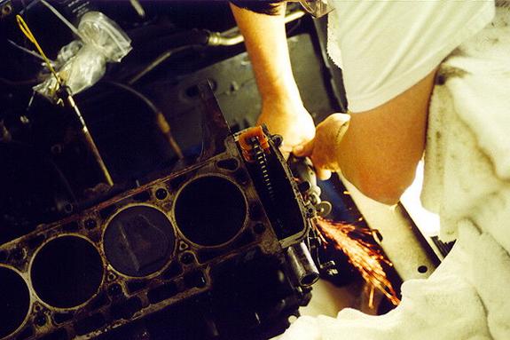
Written by Rob Anderson '00In the head, on top of the cam, there is an oil sprayer bar that directs oil to lubricate the cam and rockers. The oil spray bar bolts are hollow bolts through which oil passes through, into the oil sprayer bar. Now, these bolts tend to come loose in time from vibration. This can happen in as little as 20k miles, or as long as 150k miles, there is really no "set" mileage that this happens.
BMW has issued a new bolt to fix this problem. Really, what it is is the same bolt with a tad of locktite on the threads. But it is a new partnumber and the old bolt (with no blue locktite) and the new bolt are differentiated by a round circle engraved in the head of the new bolt. The part number for these bolts is 11 42 1 738 621.
Any good (i.e. knowledgable) BMW mechanic should know about this problem on M30s. And whenever you get a valve adjustment (which should be every 15k miles or 1-2 years), the mechanic should check the torque on those bolts. So long as you do that, you should have no problem. Even with the "old" bolts.
BTW, a valve adjustment on these cars should run around $100, give or take. This includes a new valve cover gasket. That is the only repair that I'd take, and have taken, my car to a mechanic to. You really need to get a "feel" to adjust the valves on M30s. It's an art in itself. But if you do do it yourself, you have to do with the engine stone COLD, because otherwise you won't do a good job. (Leave it sitting overnight). Oh, and you will also need a method to turn the engine (remote starter, big socket and wrench to turn crankshaft rotating nut, etc).
Written by Chris Graff '01The best way I have found to get a lot of NORMALLY ASPIRATED power out of an M30 is to do the following.
There are many places and wishes from where one can start. People may have Alpina or Hartge motors to start with, or want to keep as much of the original head/block as possible to have a 'numbers matching' car.
The pathway to a high-power M30 depends on the end-goal. The 3.5 liter racing motors in the 70s produced nearly 400 bhp, but are anything but streetable. Whereas the last incarnation of the production M30 had 208 bhp (US) and was a very smooth operator in the 3600 lb E32s.
For the purposes of this article, we will divide the �horsepower goals� into 4 divisions: 210-240, 240-260, 260-280, and 280+. 210-240 bhp is a reasonably easily achievable goal without a large outlay of cash.
A few options include the following:
Options for 210-240 bhp range:
Start with a euro B34 high compression motor or a B35 motor. Modifications include: Headers and full dual 2� exhaust, B35 intake manifold with port matching, larger throttle body, 19 lb-hr injectors, updated chip. Reasonable estimate of power is 230-240 bhp. Hartge and Alpina were able to get this type of power using Motronic and L-jet in the 80s, keeping the stock displacement. Other options include a MAF. Similar figures can be obtained from a M30 B35, albeit probably not quite as high due to lower compression ratio. 230 bhp is a reasonable estimate in terms of bolt-on modifications for a B34 HC or B35 motor. The best that a B34 low-compression motor can do with simply bolt-on modifications (chip, exhaust, intake, injectors) is perhaps about 200-210 bhp. The problem is that upgrading the cam will not benefit you due to the low compression.
Typical costs (estimated total: under $2000):
Header: $500 + additional fitment work downstream
B35 intake manifold: $200
Chip: $200 (new)
Injectors: $250 (new)
MAF: $600-1000 (new, est.)
Options for 240-260 bhp:
This range of power effectively requires head work, and preferably a bump in compression ratio. Ideally the compression ratio would be 9.5:1 or higher (the euro B34 already has 10:1, but the B35 has 9.0:1). Running a stock chip on either the Motronic 1.0 from the euro B34 or the Motronic 1.3 (recommending the 179 ECU) is probably reasonable if your compression ratio bump on the B35 is only to 9.5:1. Headwork ought to include the standard larger intake values (47mm) and preferably the exhaust valves (to 38mm). A camshaft is a must, preferably 284 degree Shrick or equivalent. Replacement of valvetrain components is always recommended. Porting and polishing the head is also recommended. At this point the B35 intake is recommended, although Alpina claimed 254 bhp using the holder style intake. Headers are a must, as are dual 2� exhaust all the way. MAF conversion is a good option, as are big-bore throttle body. Note, both Alpina and Hartge used >10:1 compression to get over 250 bhp. And Alpina used Motronic 1.1/1.3 on its later motors with 254-260 bhp.
Typical costs (estimated total: $5000-$7000):
Header: $500 + additional fitment work downstream
B35 intake manifold: $200
Chip: $200 (new)
Injectors: $250 (new)
MAF: $600-1000 (new, est.)
Camshaft: $400 (custom grind)
Head work: $2000-3000 (see Top End Performance website)
Pistons: $1000 (see JE Custom pistons)
Wiring harness and ECU: $400 (used, estimated)
Throttle body: $200 (service, based on Big Coupe Group list)
Options for 260-280 bhp:
On top of what was said above, now�s the time to consider a full B35 intake, 47/39mm valves, increased displacement, dual 2.25� exhaust and headers, big bore throttle bodies, 24 lb-hr injectors, and FI system updates/modifications that can include going to a newer Motronic, custom chips, MAFs, or other options. Over 10:1 compression is a must in these cases. Reworked combustion chamber shapes, a la Alpina, can also be considered in this case.
Typical costs (estimated total: $7500-$10,000+):
Header: $500 + additional fitment work downstream (more than $1000)
B35 intake manifold: $200
Chip: $200 (new)
Injectors: $250 (new)
MAF: $600-1000 (new, est.)
Camshaft: $400 (custom grind)
Head work: $3000-4000 (see Top End Performance website)
Pistons: $1000 (see JE Custom pistons)
Wiring harness and ECU: $400 (used, estimated)
Throttle body: $200 (service, based on Big Coupe Group list)
Tuning services: varies
Suggestions for 280 bhp+:
On top of the above: increased displacement and mild stroking, reworked combustion chambers, individual throttle bodies. At this point, 10.5:1 compression is probably required, as well as custom-tuned FI system. MAFs are highly recommended.
Typical costs (estimated total: $10,000+):
Boring motor: $400-600 (estimated)
ITBs: $600 for adapters, $500 per pair of ITBs, estimated $600-800 in additional components (fuel rail, plenum, etc)
�Clean sheet� option:
However, for the purposes of this whitepaper, we will assume to start off with an M30 B35 motor, and build a streetable, reliable, but high horsepower M30. Let�s take for example the E34 535i, or a late E24 635CSi. Concentrating on the block, there is not much you can do with stroking, but there is a lot you can do to bore the motor. There is the option of using a 3.8 S38B38 crank, or machining your own custom crank to stroke a motor. However, an M30 already develops boatloads of torque, so the better option in this case is to bore it to increase displacement and thereby concentrate on making more horsepower rather than torque. The options to boring are basically anything between 92 and 94.5mm (S38 B38 specs). It is known that the S38 B38 had some cylinder wall thickness issues, so maxing out at around 94mm bore is probably preferable. Of course you can use 93.4mm and keep a stock BMW dimension (e.g. S38 B36 specs). Therefore, Custom JE forged pistons that raise the compression to at least 10:1 and have a 94 mm bore. Raising compression is going to be a function of fuel use and head work. If you're using a B35 head and premium fuel, you can probably safely raise compression to around 10.5:1 (Alpina had these ratios in the mid-80s, but with a highly reworked combustion chamber.). If fuel quality is a question, or you don't want to be too aggressive, then 10.2:1 to 10.4:1 is a very reasonable compression ratio for these motors, especially if you are using a piano-top style piston profile as opposed to the heavily reworked Alpina style cylinder heads and pistons. However, the stock Motronic 1.3 will ping if you bump the compression by 1.5 points, therefore you will need to retard the timing that BMW built into the 1.3 with 9:1 compression.
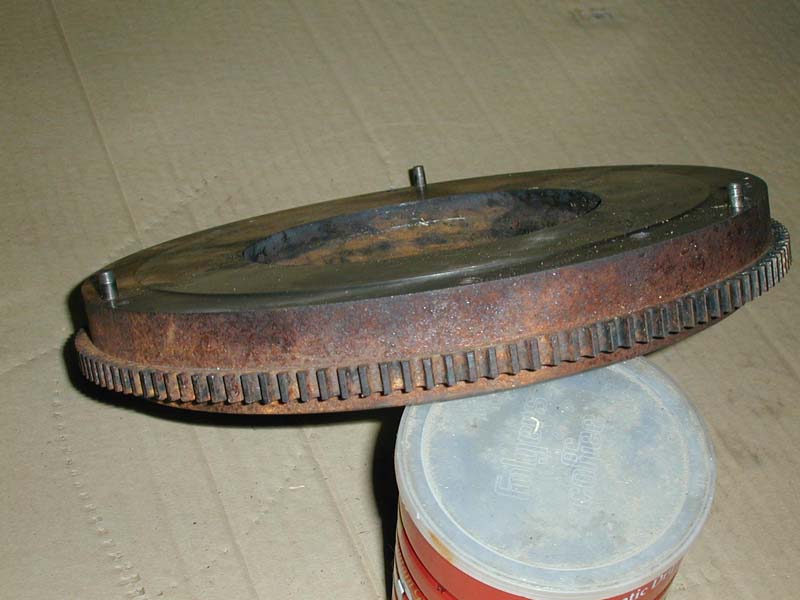
Recommended Top End Performance can get JE Custom piston with Total Seal Rings which are far better than BMW's rings with just about any shape and compression ratio you want. They have blueprints and records and can do anything you want. Now, radius the con rods as that will increase strength. Of course I suggest using new con rods bushings and bearings. Custom, strengthened, and lightened con rods are available from Top End, should you go this route. Use the stock 86 mm stroke crank, but have it cross drilled and rifle bored, if you can. This will increase low end oil pressure and also the life of your rod end bearings which is a good thing because you will be making a lot of power. Now, you start to assemble the bottom end. Pistons, rods, crank. Then you get to the oil pump. You need to use an E28 oil pump because without it, you will not be able to bolt on the E28 oil pan which is necessary to clear the subframe in an E28 or E24 (that is if you're starting with a E34 or E32 engine). Now you have the bottom end built. I suggest using a lightened flywheel also from Top End Performance. 15lbs is light enough and an M5 clutch should do you. There have been people who�ve gone for 12 lb or lighter flywheels with success, albeit these are non-AC equipped cars. The later Motronics can probably handle the idle better too if you go for that light a flywheel.
Now that you have the bottom end together, it is time to work on the top end. Let me just say, that with the bore increase you will have a 3.58L motor. Also please don't forget it is important to use the E28 motor mounting arms so you can bolt the block to the subframe. I also suggest using 2 of the left side motor mounts from an M5 as they are stronger than the stock units (or the M535i mounts as those should be the same). Be sure you do not �He-Man� torque them, as this will shear the rubber mounts. Speaking of torque specs, it is vitally important that one follows them! Do not under any circumstances over or under torque critical fasteners such as on a motor. Always follow the BMW torque specs.
As for the head, use a stock B35 head to start. It�s now time to invest in machine shop experience, and begin by skimming it to make sure it is flat. Port and polish it, and also do a three angle valve job � most engine builders who specialize in older BMWs and race motors can effectively do this service. Depending on what cam you are running you might want larger valves but I think that the 47 mm intake and 38 mm exhaust are just fine (although 47mm / 39mm will do you well too). Top End Performance again has loads of experience here and can make custom stainless steel valves for you. Anything larger than 47 / 39 will require custom valve seats and more headwork to get them to fit correctly. New guides, seats, etc. are a must. Then radius the (new) rockers which will give them added strength for the extra duration and lift of the cam. Now I suggest using Metric Mechanic progressive rate valve springs (Edit: the dual valve springs from MM are no longer available, and thus we'd recommend going with dual valves springs that Top End sources) and also their head oiling upgrade kit (which is a crimped oil sprayer bar to improve oiling a the cam). You can use titanium retainers if you like, depending on the RPM you�re expecting out of the motor this might be more or less beneficial. You can use pretty much any cam you want, but I suggest not going below a 280. Using a Shrick cam design (284 or 292) on a custom grind is preferable. Top End can provide these, as well as almost any other good engine shop with experience in BMW motors. An adjustable cam gear will let you advance and retard your cam for better performance or better economy. This might be particularly useful in final tuning.
For the head gasket, I believe you can use the early big six, with the 93.4mm bore gasket, but I would suggest getting a custom one with a solid metal ring in it so that you have less chance of blowing the gasket. These are again available at almost any good custom engine builder shop specializing in BMWs (e.g. Top End). MLS gaskets have also been recommended, but have a strict requirement for surface finish RA. Cometic have a good product that works well with older motors, particularly M30s.
On to the intake and exhaust... For the intake I would suggest starting with the E34 M30 B35 intake, and then port match it to the head. Extrude-hone will cost a pretty penny, but will give you the maximum flow possible out of the stock casting. As for the exhaust, custom headers are in order that have 1 1/2" ID primaries that go into dual 2" collectors at minimum. Custom track pipe to mate up with the collectors and I'd recommend an E28 M5 exhaust if possible. These exhaust dimensions are basically the minimum you can run...although it'd be preferable to run something slightly larger. A good tuning book (e.g., A. Graham Bell's "Four Stroke") should offer some insight into a custom exhuast. You should also be able to use the E24 M30 b35 intake bracket to support the intake to the block.
There are two options for a individual throttle body system. The first is to attempt to retrofit the M5 intake system. This requires at a minimum fabricating adapters from the head to the M5 intake runners. It also requires investigating the choice of fuel rail, as the M88 or S38 rail and FPR will not clear the t-stat housing on the M30. Similarly, the TPS switch will have to clear the t-stat housing. To do this the adapters have to be angled so as to point the intake runners above/below the t-stat housing and rad hose. The other option is to get the Weber DCOE adapter brackets from Redline Weber (Redline Weber part # 99004 094). The castings aren�t that great, so porting and polishing them is a must. However, 40mm or 45mm Weber fuel injection ITBs can then be bolted onto these. Again, one of the flanges near the t-stat housing has to be shaved a bit to clear, and I have not verified if the TPS switch will clear the t-stat housing and rad hose, but this looks to be more a �bolt-in� solution. Additionally you�ll need a custom intake plenum. http://www.jameng.com and http://www.twminduction.com are both good sources for the ITB components, as well as Top End Performance can order anything from Redline Weber.
Fuel system and engine management: Use either custom engine management (Megasquirt, etc.) or Motronic 1.3 out of the late '88 and '89 E24, along with the engine harness. Update the ECU to #179 (#150 is Motronic 1.1). This is because the Motronic unit will then mount in the same place as the one currently in the car, and Motronic 1.3 is adaptive enough to run this motor well. It is necessary to retard the timing a bit as the 1.3 was set by BMW with 9:1 compression, although this seems to be an issue (pinging that is) at lower rpm, high load conditions, for engines with ~9.8:1 compression or higher. I would then suggest a dyno day and a custom burnt chip. As for fuel system, I suggest running Mustang 24 lbs/hr injectors at minimum at 3.0 bar, but depending on your fuel requirements you may need to up that to 27 or 30 lb/hr. The Bosch Motronic 1.3 in limp-home (open loop) mode with the 179 ECU and 24 lb-hr injectors runs my (Chris�s) engine around 11.8-13.0:1 AFR, or very rich. Idle is right around 14-14.5:1, and off-idle there is no hesitation. And the 3000 - 3500 rpm range is butter smooth. Cam seems to �come on� around 3700 rpm, although after 100 miles of break in I�ve not yet gotten past 4000 rpm, nor gotten past � throttle.
I would also suggest using a big bore throttle body because you will need as much air as possible. On this note, a Mass Air Flow Sensor conversion is in order as it will give the engine management more precise readings and also will be less of a restriction, in theory. There are and have been a number of options for MAF conversions for Motronic systems. However, it is important to note that a MAF will not in and of itself improve outright power, given similar flow conditions at wide open throttle vs an AFM. That isn't to say a well operating AFM isn't good as is - one has to remember that BMW used a AFM on the euro M5/M6 to great effect to get 286bhp. The E34 M5 3.6 increased power to 310 bhp, but included improvements to the head, increased displacement, a more complex intake resonance system, and better engine management system with O2 sensor feedback, all on top of going to a MAF. And the improvement was only 24 bhp. Alpina also got 260 bhp (DIN I believe, at the crank) out of their B10 3.5 liters using an AFM. The conclusion is that, in theory, a well operating MAF will provide better on/off throttle smoothness, and part throttle improvements. If you have a well operating AFM, unless one goes to standalone fuel injection system, it is not necessary to get a MAF. But in theory, a well operating MAF can provide some improvements over a AFM.
With regards to cone filters, their maintenance IS A MUST. Never leave a K&N or similar filter un-oiled. However, a stock air filter system works just as fine as well. Lots of work can be done here to 'dress up the engine bay' since a cone filter in and of itself will not do you much good in terms of power. Additionally, an oiled filter fitted too close to a MAF will ruin it in short order.
As for oiling system, I would try to run the euro E28 oil filter canister and housing because I would never run this motor without an oil cooler, which BMW's bolt on approach here will work just fine.
Rob and myself have built an engine very similar to the 'clean sheet' recommendations we have written above. These are a summary of the results as of October 2007:
Engine rebuilt with following specs:
� M30 B35 out of E24
� 10.45:1 custom JE forged pistons, total seal rings
� M90 head gasket
� Bored to 93.4mm (3535cc total)
� New con rod bushings, bearings, main bearings, etc; rods and pistons balanced to within 0.7 grams of each other
� 15 lb Top End Performance flywheel
� Larger, stainless steel valves (47mm / 39mm)
� Ported and polished intake and exhaust ports
� 3-angle valve job; new seats, new seals, etc.
� Metric Mechanic peened rocker arms
� 294 deg custom ground cam (Top End Performance, style 290MM)
� Dual valve springs, titanium valve retainers
� All new valvetrain components
� Hartge Headers (yet to be installed)
� Custom, dual 2.25� exhaust with high-flow catalytic converters (yet to be installed)
� Motronic 1.3, with custom burnt chip (Mark D�Sylva)
Future project tasks (as of October 2007):
� Custom tuning with Mark D�Sylva using EPROM emulator and Innovates DAQ, once engine is broken in
� Finish custom exhaust
� No full dyno sheets until engine is fully broken in! (A 3000-mile process)
Updates:
Dec 2007: Mark D'Sylva has burned an equivalent of an Alpina B10 3.5 chip for the motor and we have installed it to great effect. The fueling maps are spot on (as shown above). And we will be letting the motor run closed loop as soon as the data logging systems are in place. The response in the engine is very smooth and progressive so far up to the 4500 rpm break-in imposed rev limit (we only have 300 miles so far on the motor). The ignition timing is far more retarded than the stock chip, although we have gotten on the verge of pinging at 2000 rpm-3000 rpm in 4th and 5th gear at higher loads going up hills (not fuel ping, but timing ping, as you can tell the chip is trying to advance the timing under the load and conditions). Nonetheless the engine can be driven around on a 'normal' basis and the chip works very well. Idle is at 1000 rpm upon initial installation. More updates to follow after the 300 mile break-in service (valve adjustment, oil change, etc).
Jan 2008: The 300 mile break-in service was complete. Motor is now running closed loop (O2 sensor connected). The idle is a but lumpy, but better than before the valve adjustment, and not unexpected with the cam and lack of headers. Also the Evap valve is operating and I needed to close off the supply hose since I have no evap cannister on my car. Fueling is spot on. It's noticeable how the ECU is learning/adapting as I drive the car more.
Jun 2008: Installed the knock sensor (Knock Link) to monitor pinging. Pinging under load can be heard/measured in higher gears (3rd, 4th, 5th), when leaning on the throttle from 2000 rpm on. Basically I figure that at >75% or >80% throttle, in those conditions, the timing is too advanced. Fueling has been spot-on since O2 sensor has been connected.
Nov 2008: Innovates LM-2 has been installed and now I can collect data. Engine has 600 miles on it - yes, I know, but I've been far too busy with work since the summer. I did an acceleration test run through 3rd gear on the street, short shifting at 5000-5500 rpm. With a 3.73 diff, and OD gearbox, I hit 60 mph at about 4250 rpm in 3rd gear. During the test, I only accelerated to about 80% throttle, since I was on the verge of pinging in 3rd gear. 1st and 2nd were not full throttle, but hard to say exactly what percentage.
Dec 2008: Replaced spark plugs from W8LRC to W8DC at 600 miles. Old plugs seemed to be operating within temp range, but some cylinders had some carbon/ash deposits that had not burned off - combination of rich running and cold starting, I figure, from the lack of use/driving the car saw over the summer/fall of 2008. Have purchased a chip emulator and will test a few custom files that will have backed off the timing to see if I can get the pinging to stop under high load conditions in the upper gears. 700 miles on motor so far...500 miles to go until the 1200 mile service to be done in January.
Sep 2009: In the spring of 2009, while having the engine in for it's valve adjustment and oil change, it was noticed that the intake rear rocker shaft was misaligned. Further investigation revealed that the wrong shaft was installed, and the head had to be removed and reassembled. In addition, the MLS was leaking slightly from the front edge on the exhaust side. This was replaced with a stock BMW M90 head gasket (actually a thicker one, as I wanted to lower the compression from the 10.6:1 to 10.45:1 to help the pinging). Car was finished in June, and I drove it on a 500 mile trip in September to finish the break-in. Oil consumption was 1/2 quart, plus the addition of another 1 quart in the process to refill all the head crevices from the engine rebuild. More data was collected, and it is possible to hit full throttle in 1st, 2nd, and 3rd in most cases. 4th and 5th still pings. AFM voltage indicates I'm getting near full flap open at 6200 rpm. I also replaced the spark plugs with the W7DCs, since the W8DCs indicated they were running too hot, and I needed to get a colder plug. That is unsurprising since Alpina ran the W7s in their B9s and B10s. Motor has 1450 miles on it now.
Written by Rob Anderson '01 (Edit: Chris Graff '06, �07, '08)
Some results on engine conversion
Based in large part on our discussion about engine building, I'm very pleased w/ the results of my b34-b35 combo.
Running the older Motronic I produced 206 hp and 219 ft lbs with the new motor. The old stock (w/ JimC) motor, on the same dyno 18-20 months earlier was 156/164 as I recall.
Torque comes on around 3400 and lasts thru peak HP at 6200. Shifting at peak drops me into the torque band and all's well.
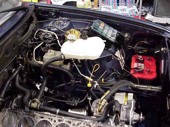
Dyno done late '02The M5 and M535i have oil coolers, even the Euro 535i has an oil cooler, so why doesn't mine? Well it does now. I spent a lot of time looking into putting in a oil cooler. The one main problem I ran into was the fact that no aftermarket housing would bolt onto the block. This means that the oil filter housing has to be replaced with one from one of the previously mentioned cars, and M635csi and M6 and Euro 635csi(post '82). These are not very easy to come by and are very expensive from BMW.
I was able to find a used housing off of an M5 and then started at a cooler. I orignially purchased a Euro 635csi cooler and lines. This cooler fit in to the car, but the lines did not come close to fitting. I then looked into replacing the lines with ones from a US M5, but I found that the design of the M5 cooler is different than that of the Euro 635csi. I then looked into getting a cooler from an M5, but those aren't easy to find. So I found that a 524td has the same oil cooler as an M5!! But the coller lines are not the same. I looked into what lines to use. I thought that I might be able to use a Euro 535i or M535i line, but since I have the big US bumpers, they won't fit.
I then looked into what car has US bumpers, and an oil cooler. The only car is the US M5. Then with a quick check of part numbers, I found that the US M5 has diffferent lines than any other 5 series. I also was able to find an M5 that I was able to look at and found that behind the airdam the US valance was still fully intact. This gave me the confidence to purchase the expensive M5 oil cooler lines and install the cooler. The installation was fairly simple, but required the removal of the aux. cooling fan, and the front grills. The lines were the first things to go into the car, and require the bending of a small tab from the lower valence down. Once the lines were in, I placed the oil cooler in the car. I had to make custom brackets to hold the cooler, but once that was done, everything bolted together. I made sure to put oil into the cooler before I bolted everything together so that I didn't have a lack of oil pressure when I started the car. Now the car has a cooler and I see lower oil and water temperatures.
Written by Rob Anderson '01
M30 B35 and B34 Cylinder Head Differences
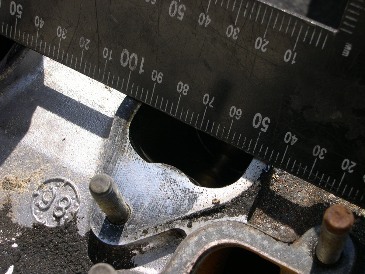
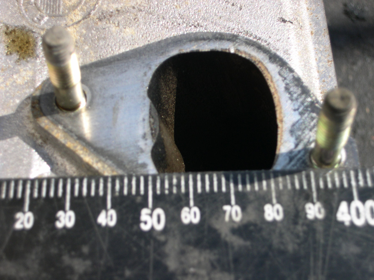
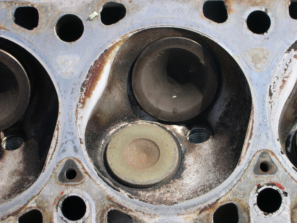
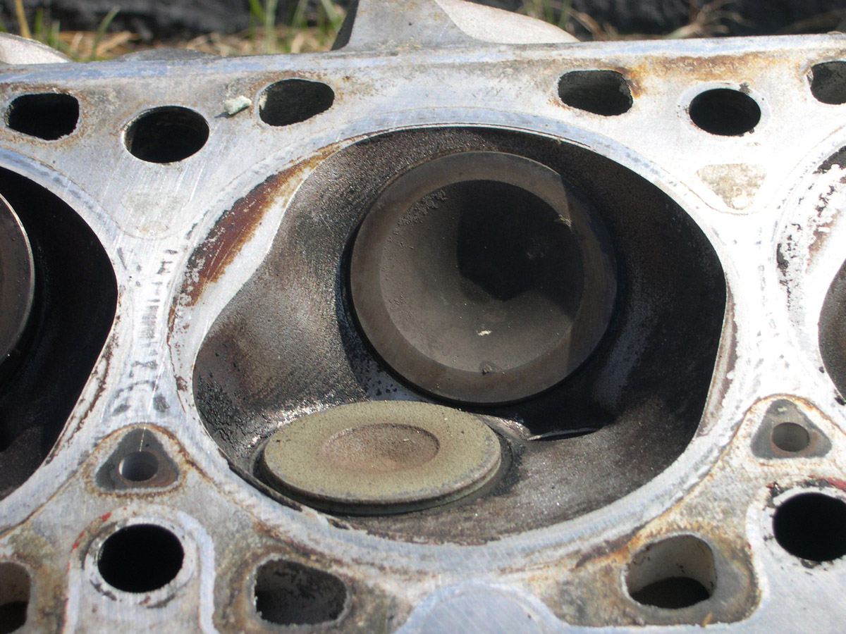
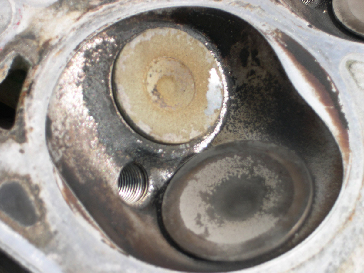
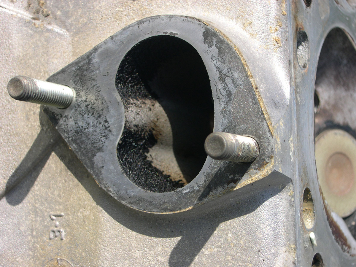
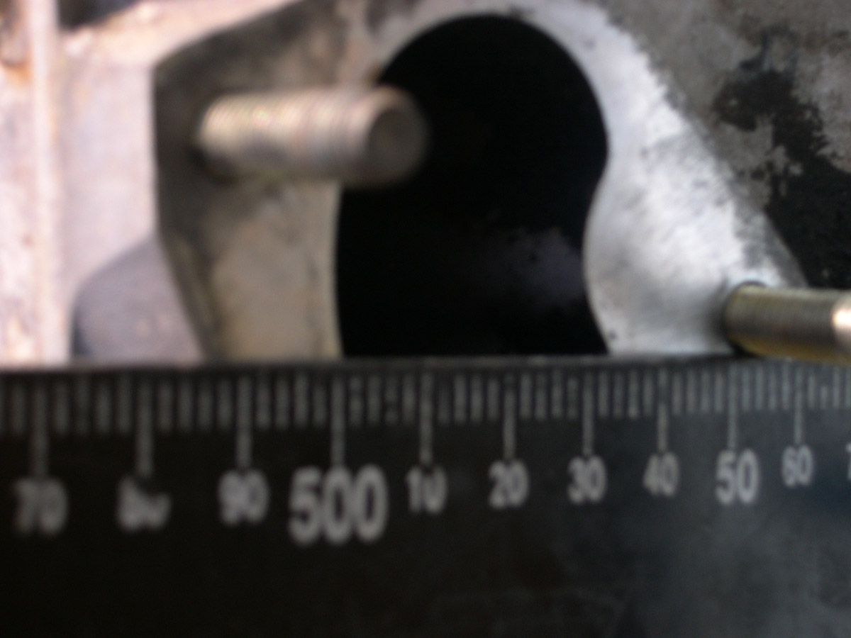
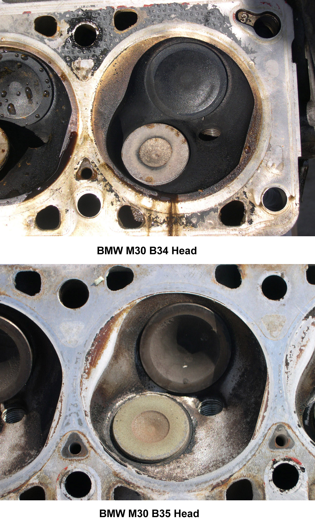
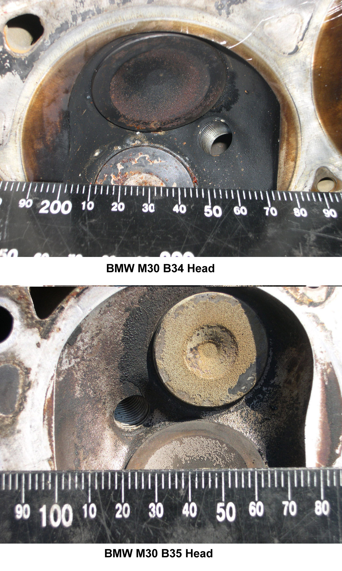
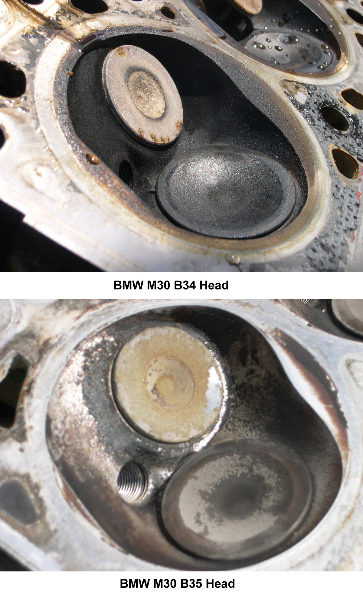
There were a few major difference between the early B34 engine (3430cc engine found on the E23, E24, and E28, between the dates of 1982 and 1988, depending on model) and the B35 engine (3430cc engine found on E24, E32, and E34 models between the dates of 1987 and 1993, depending on model). The following photos show the B34 and the B35 engine cylinder head and intake ports. The basic differences between the B34 and the B35 engine are as such:
The photos show the difference in the combustion chamber volume and shape. There is more "scavenging"; or volume around the inlet and exhaust valves in the B35 head. Also the B35 head has smaller ledge/overlap at the edge of the head over the piston. Note the distance between the headgasket edge and the edge of the combustion chamber.
B34 Engine Picts:
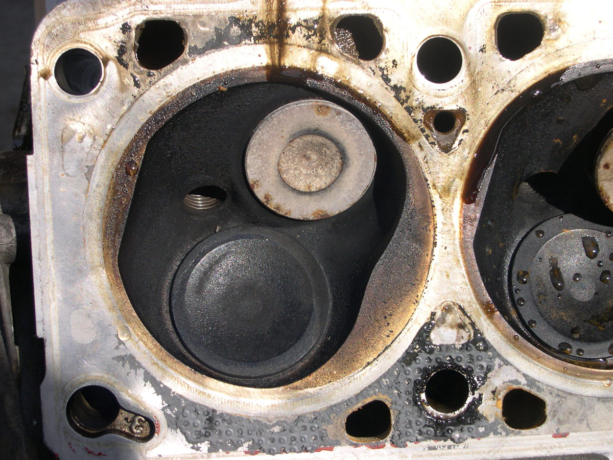
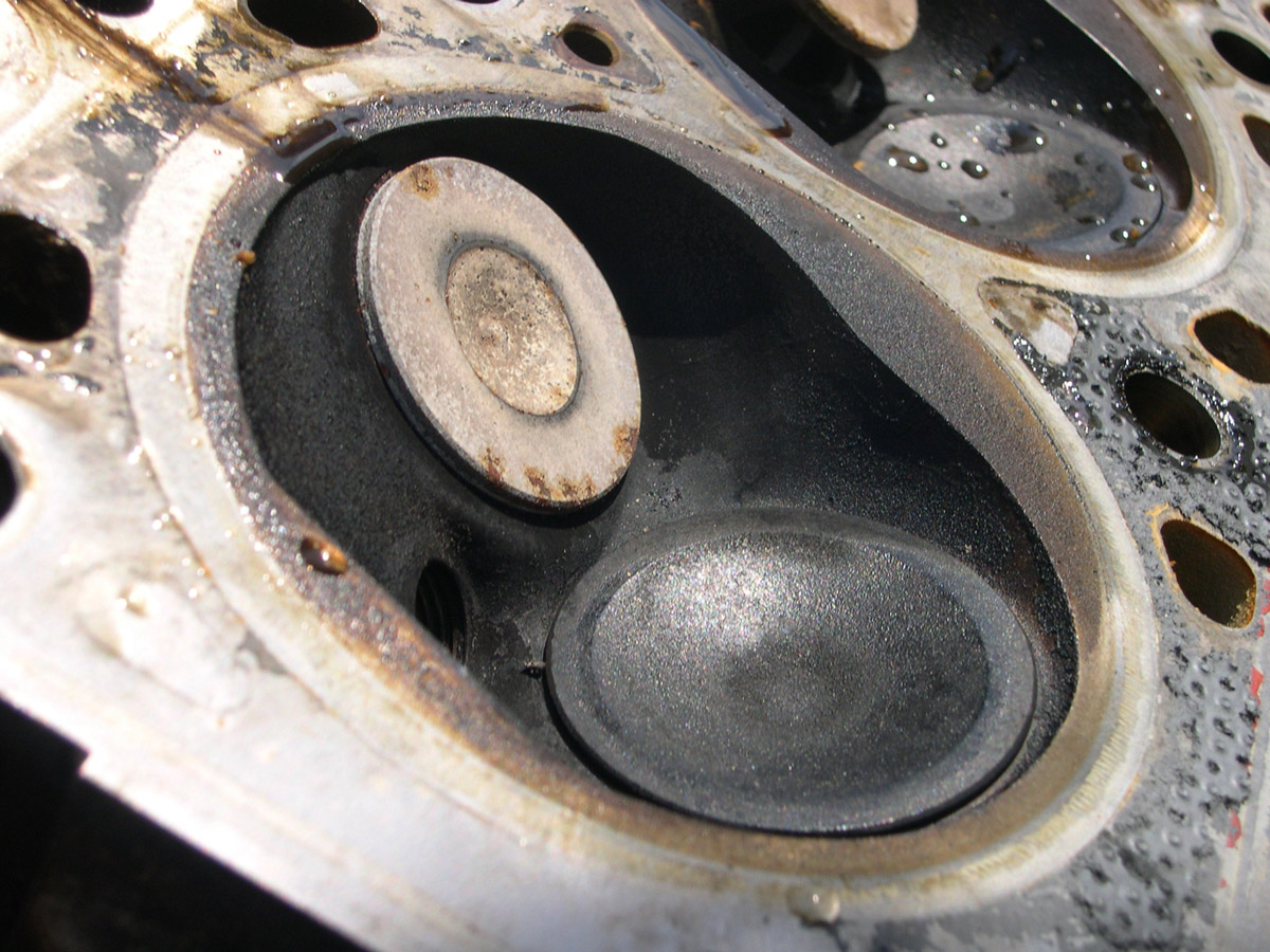
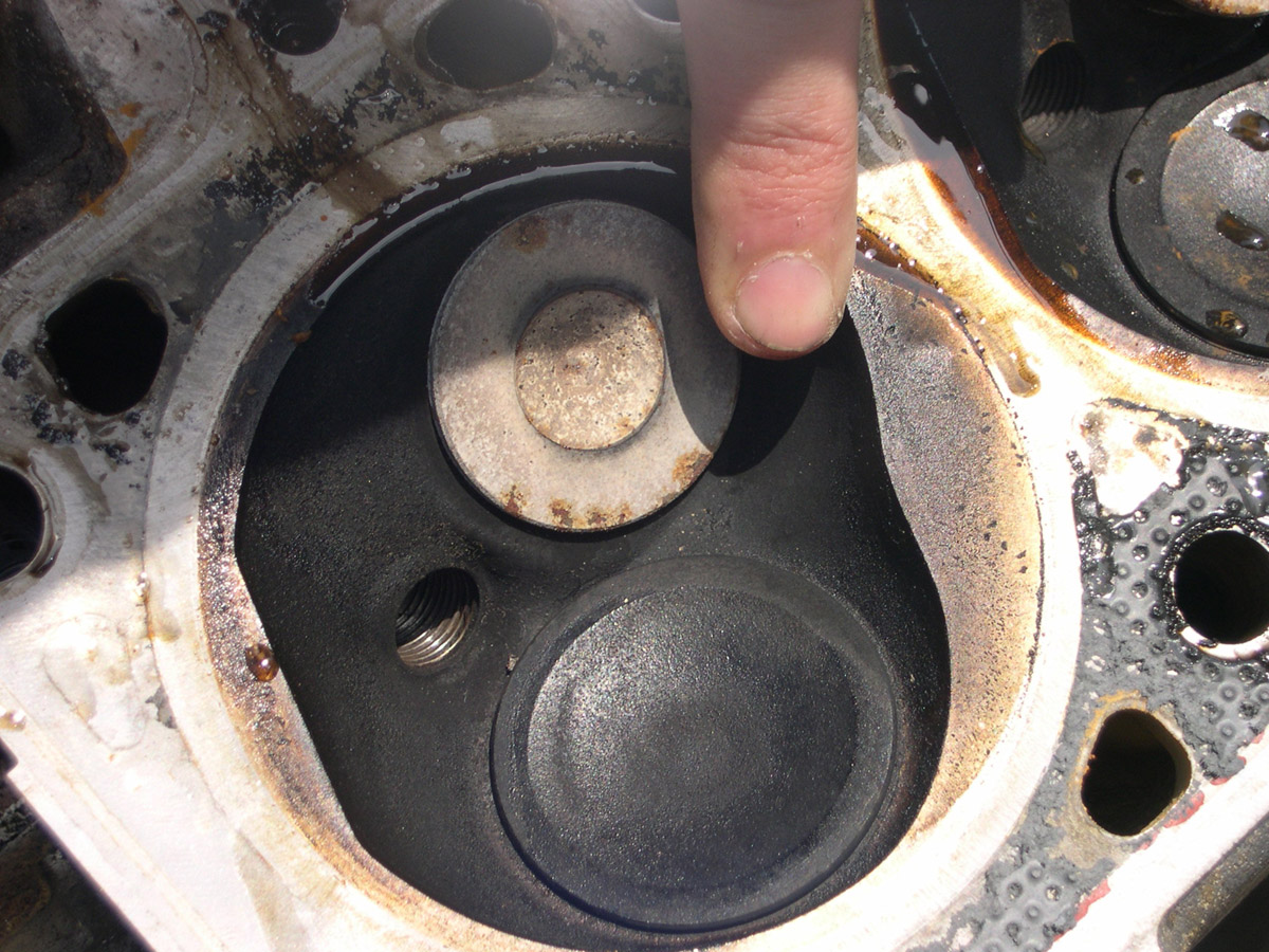
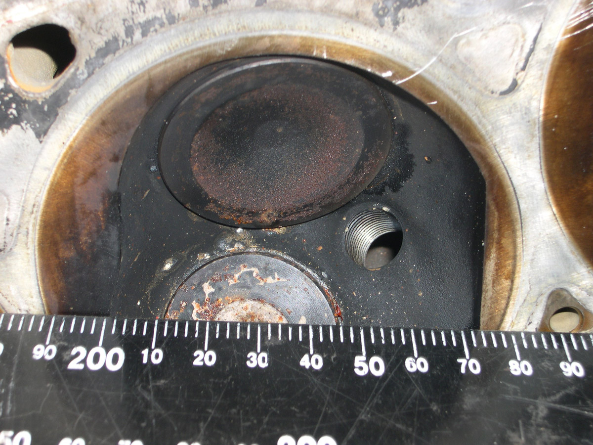
B35 Engine Picts:
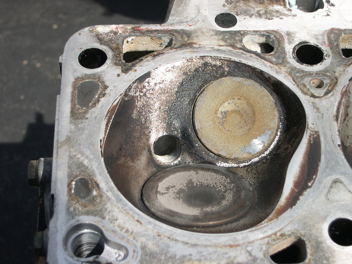
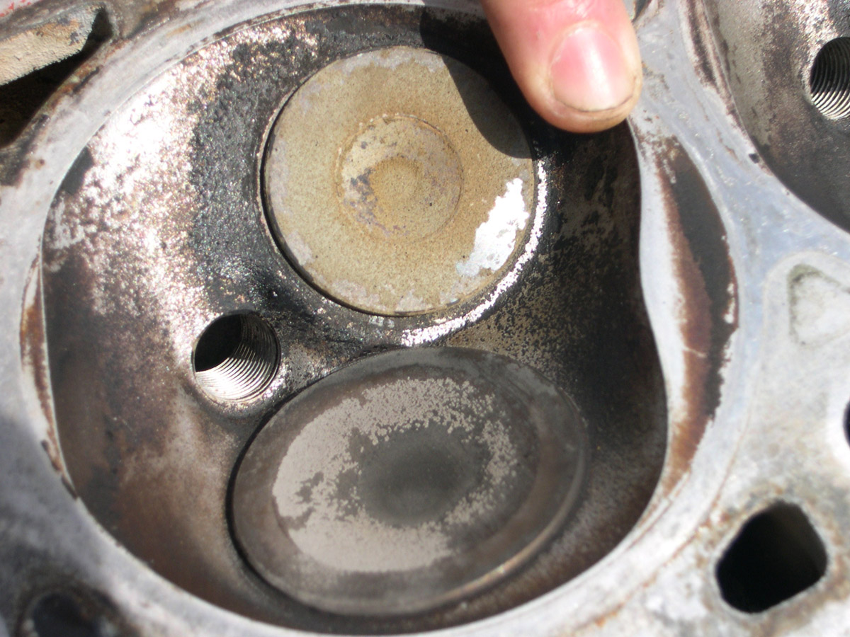
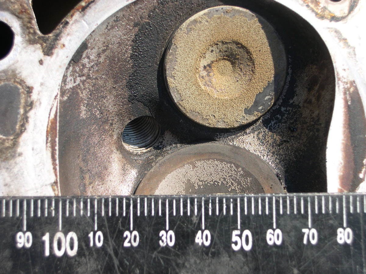
Comparisons
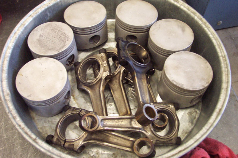
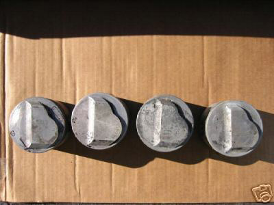
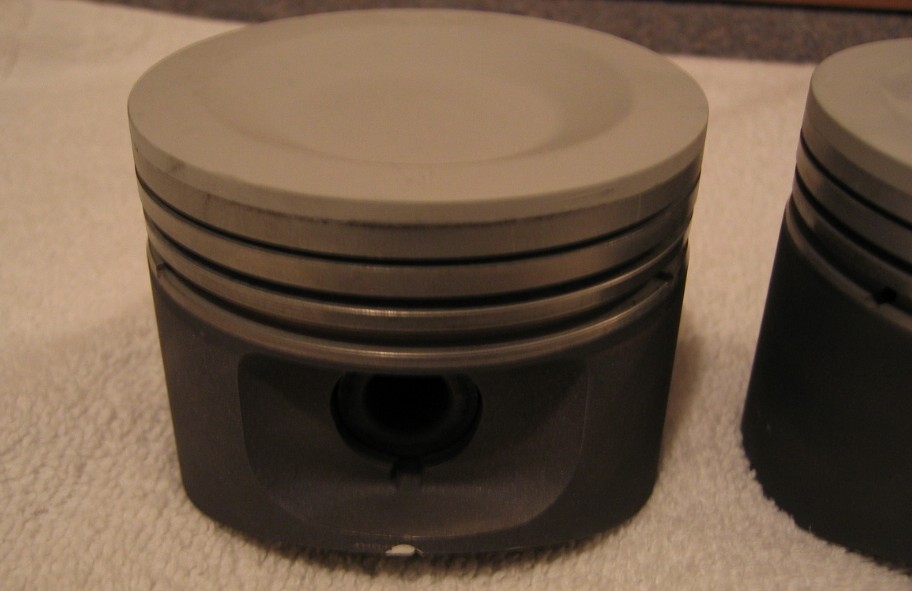
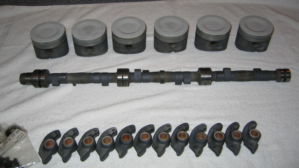
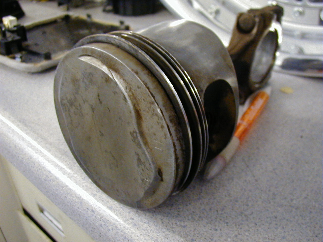
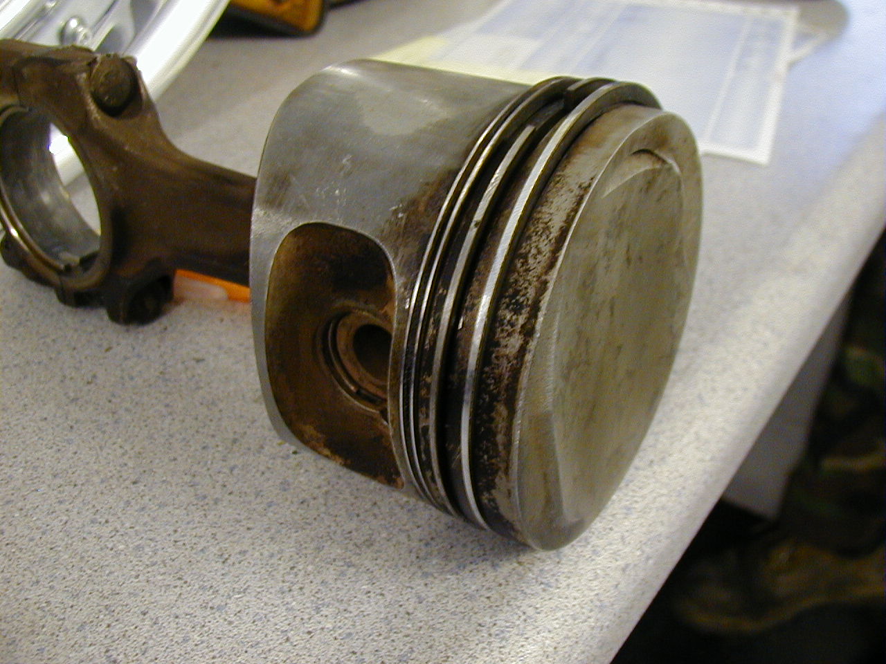
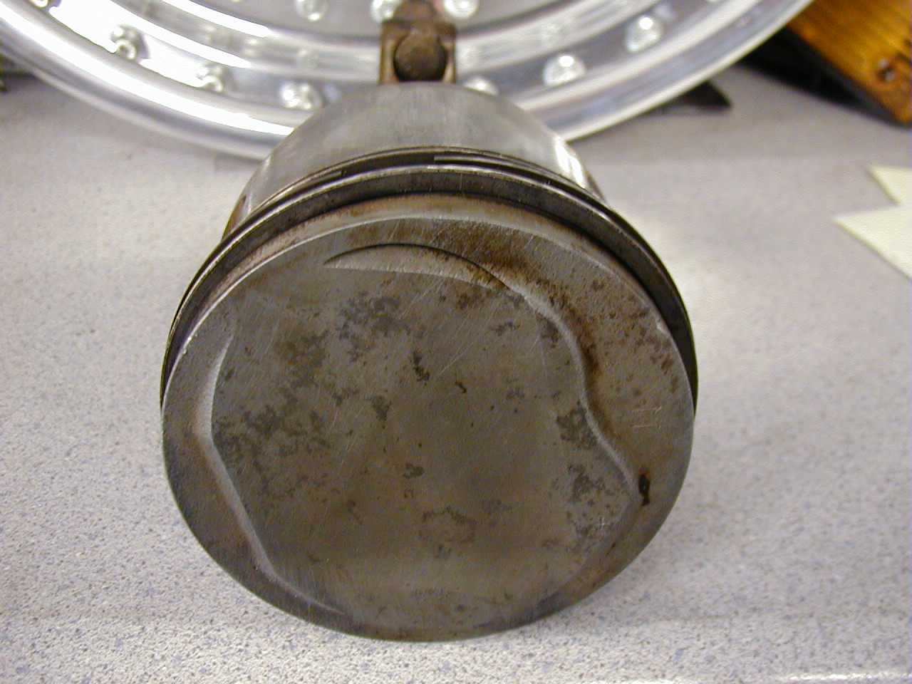
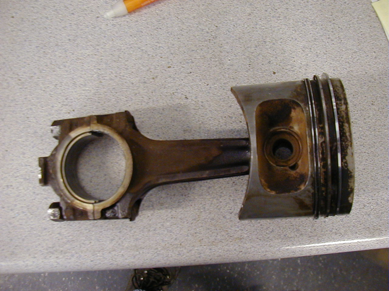
The pistons on the B34 engine are either an 8:1 low-compression piston, or a 10:1 high compression piston. The 8:1 pistons have a deep dish, and are cleary recognizeable. The 10:1 pistons have a dome, with a grand-piano-esque shape. These are shown below. The B35 engine has 9:1 compression pistons, where the shape of the dome is much better for combustion characteristics. The edges are pushed up, while the center of the piston remains lower. This allows the combustion chamber shape to be much more rounded, and thus with the differently shaped head allows for better combustion, squish, and swirl characteristics.
Piston Pictures:
M90 piston (M30-family); 3453cc engine (found on E12 M535i, early E24 635CSi)
2002 High compression pistons. Dome form similar to B34 high compression dome
M30 B34, high compression pistons in engine (1st engine bay photo)
M30 B34, high compression pistons in engine (2nd engine bay photo)
M30 B34, low compression pistons 1 (these are M106 turbo pistons, but shape and compression are similar)
M30 B34, low compression pistons 2 (these are M106 turbo pistons, but shape and compression are similar)
M30 B35 pistons, photo 1
M30 B35 pistons, photo 2
M30 B35 pistons, photo 3
M30 B35 pistons, photo 4
Thank you to Duke Samouce and Jim at Autobahn in San Diego for the pictures of the pistons. Thank you to Todd (TCD, Turbo Charging Dynamics) for allowing me to photograph the B35 and B34 heads.
Written by Christopher Graff '04
M30 Oil Pan Removal
The easiest way is to lift up the passenger side of the motor, off of the motor mount. I have the front of the car on ramps and then use a floor jack, raised up on wood under the oil pan, also using wood between the jack and the pan. Then, I lift the motor off of the passenger side mount by jacking up under the oil pan after the motor mount retaining bolts have been removed. Once I have gotten it up a good distance. I got mine so that the head was just touching the firewall. I then put a jack stand under the AC compressor bracket(make sure you put it under the side that does not need to be moved, or remove the part of the bracket that is in the way before starting the jacking). The I lower the motor onto this jack stand. Remember, it will take a little while for the motor to come off the mount because you are basically removing a lot of weight from the front of the car so the suspension will decompress. Once you have done this, then go about removing the oil pan bolts. Once you get all of them out, the pan will drop, but you won't be able to pull it out. You need to reach into the crack between the pan and the block and remove the oil pump from the block and most importantly the sprocket at the front. Once you have done this, the oil pump should drop into the pan. Then you should be able to remove it no problem and accomplish any work you need. To install it, it is the reverse of removal. Make sure you have the pump in the pan and put them up together, because they won't go in separately.
Written by Rob Anderson '01Please Projects page.
The Ultimate Motor Swap
Ok, even though this is from the E30 ETM, it should be the same. Let me know if any of the wire colors are not found or different, and I will try to dig up my E28 ETM. Please note that I am partially color blind so I have great difficulty telling the difference between Green and Brown. So some wires that might be Green I will call Brown and vise versa.
The connectors that need to be taken into account are C101 and C103. C101 is the 17 pin connector that plugs into the fuse box. C103 is the connector that plugs into the motor wiring harness under the dash on the passenger side. There are anywhere from 5-3 wires in C103. The wires on the side of the body are colored, BK(to instrument cluster(tach speed drive)), BR(Ground), WH/BK(to instrument cluster(fuel economy gauge drive)), GN/RD(not used(goes to one side of the OBC relay)), GN/YL(not used(goes to the other side of the OBC relay)). Now first lets concentrate on this plug. On the E28, BK goes to BK/BL, BR goes to BR, and WH/BK goes to WH. On an E30, the 2 wires that are not used in the E28 are used, which I believe are also used on the E34. These 2 wires are what cuts the ignition control when the CODE function of the OBC is used. If you are wanting to wire these in, they should connect to the one GN/RD wire. Basically, you cut the GN/RD wire and run one side down one of the unused wires and back to the other side of the GN/RD wire. In the E28, though the OBC relay should control the no start function by cutting power to the main relay, so that is why your car runs now, so I would just leave the 2 wires that aren't connected, unconnected.
Now onto the 17 pin plug on the side of the fuse box. C101. I believe that all of the connections for C101 and C103 in the E28 are contained in the E34 C101, so you will have to do some splicing up near the ECU to put in the other end of the E28 C103. The E28 plug has listed numbers I am going to refer to these number and the wire color that should come out of it on the E28 motor and what it does.
Pin 1, BU goes to alternator. Goes to alternator "charge indicator" light in instrument cluster.The E34 uses a round style connector to plug into the fuse box. This has 20 pins so I will list what the wires in each of those do.
Pin 1, BU goes to the alternator. Comes from the Instrument Cluster "charge indicator" light. BU in the fuse box.To remove the tank, remove the fuel lines from the filler plate underneath the access in the floor of the trunk. Also remove the electrical connectors from the fuel pump and level sender. Open up the fuel filler door in the side of the car, remove the filler cap, and pull out the rubber piece that surrounds the filler neck. Now you can see 3 small lines hose clamped to 3 small metal and fragile looking pipes which are part of the tank. These 3 lines are difficult to remove. If you are replacing your tank, you don't have to be gentle about pulling them off. I think I ended up cutting the line off of one particularly stubborn pipe because it looked like there was enough line left over to reattach to the new tank.
If you haven't run the car until it is almost out of gas, I highly recommend draining most of the gas out of the tank. There is a drain plug on the right front lower corner of the tank which uses a crush washer to seal. I think it took a 5mm allen wrench to remove the plug. Try to keep the drained gas out of the nice cars. Save it for the Oldsmobuick and the lawnmower
DO I NEED TO REMIND ANYONE OF THE DANGERS OF AN OPEN DRAIN PAN FULL OF GASOLINE? HOW ABOUT THE EXPLOSION HAZARD OF A CLOSED METAL CONTAINER FULL OF GAS VAPOR?
Before loosening any bolts, put your flor jack under the tank to keep it from ventilating your skull. I believe there are three bolts holding the tank off the ground. One bolt may be partially abscured by the exhaust so you may have to loosen or remove hangars to get to it. I had to move my exhaust a couple inches to drop the tank. You may also have to remove the right side swaybar bracket. There was a bent metal clip under the swaybar bolt in my car which was blocking the tank. Remove the bolts and lower the tank. Installation is the reverse! This would be a good time to replace all those dried out fuel lines in the back half of the car.
I had a decent tank from a garage kept 528e which happened to be sitting in my driveway. Upon tremoval of the 528e tanks, I found a litle surface corrosion but nothing that caused great concern. The Maximillian price of $220US for a new tank is very good so I suggest buying a new tank instead of throwing a rusty disaster-waiting-to-happen into your car.
Written by Ed Walters '00Do you know how the system works? What it does is take the gas vapor from when the gas heats up or is poured into the tank and then condenses it and inserts it into the intake. This makes for a wet manifold as well as non-metered air entering the intake. This system was a complete after-thought from BMW and all true Euro cars don't have it. The reason why is because the US EPA wanted to prevent the gas vapors from escaping to the atmosphere. What really they are doing is creating a situation where you are getting extra air and fuel vapor into the combustion. As you will know, gas vapor does not combust as easily as liquid, and in fact is very hard to combust, and is therefore put through the cat and out the tail pipe. This increase the emissions of the car and also robs power because of the wet manifold condition and the increase in un-metered air going into the motor.
After completely understand how this system works and what it does to the operation of the motor, you will see that it has no benifit and in fact the claim you made of having your premium evaporting should happen because of the way the system works in the European cars where the expansion tank is vented to the atomsphere. What expansion tank does in European car is that it acts as a collector for the gas vapor and then once the gas vapor converts back to liquid, it flows back into the tank. This is also shown by the placement of the expansion tank in the car. The expansion tank is placed higher than the main tank and is also far away from a hot exhaust. This allows the gas vapors to cool and therefore condense back into a liquid and flow back into the tank. Thw only reason why there is a line to the outside of the car is that in cases when you are filling up the car, you are inputing more gas than air can come out. This therefore allows for the pressure in the tank to be released and so you are able to fully fill the tank. I have had this happen on a 7-series where I was filling it up and the pump stopped, but the tank was not full. This was caused by the charcoal canister system and the fact that it doesn't allow pressure to be released from the main tank quickly in situations like filling the car. Also, the possitioning of the line port on the expansion tank that runs to the charcoal canister is also at the top of the tank. If you know about chemistry, the gas vapor will settle to the bottom of the tank because of the fact that it is heavier than the normal air. Therefore, the normal air will go out of the expansion tank, and the fuel vapor will stay in. Now you are correct in saying that when you fill the car it will smell like gas for a little bit, but you are incorrect in saying that you want positive pressure in the gas tank. While positive pressure will allow for the tranfer pump to work easier, you will not be able to fill the car fully after driving. Also the charcoal canister system does not keep positive pressure in the tank. If you have ever looked at the canister and how it works, it is open to the air on the underside. This allows for the prevention of a build-up of pressure in the tank, but it doesn't work very well.
In closing, the charcoal canister system was an after-thought by BMW to abide by the EPA laws. Personally, after reviewing how the system and the problems that it cause, such as rough idle, incorrect mixture, poor emissions and difficulty in filling, I see now reason to keep the system on the car unless it is required by the emissions laws in your state.
Written by Rob Anderson '01Here are the part numbers and what they are rated at.
Stock E28 535: 19.82 lbs/hr @ 43.5psi (3bar)
Stock Mustang: 19 lbs/hr @ 38psi
The increase in flow rate is proportional to the square root of the increase in pressure. To convert the mustang flow rate to flow rate at BMW pressure:
STOCK(Sorry don't know the part number) 19 * (43.5/38)^1/2 = 20.33lbs/hr approx. 2.6% increase.
M9593A302 24 lbs/hr @ 38psi so 25.68 lbs/hr at 43.5psi approx. 29.566% increase.
Now it all depends on how much power you are going to be making. My thought is that if you will be getting close to 260, so you will want an injector that can handle that amount of power at 85% duty cycle. Since the stock injectors can handle 240 on lets say 100% duty cycle. So, a 19 lbs/hr injector from a Mustang which would be a 20.33 in our car, you will be able to put out 3% more power at the same duty cycle. So you will be able to put out somewhere close to 247hp. Now lets go to the 24 lbs/hr injector which is 25.68 lbs/hr in our cars. That gives you a 29.566% increase which means that it can support 311 bhp. Now you only want to be running at about 85% of that so, at 85% duty cycle you will be able to support about 264hp. If you find that the car is running too rich, then you can always lower the fuel pressure which is very easy. You just use a 528e fuel pressure regulator, which is 2.5 bar.
Written by Rob Anderson '01This is my opinion from personal experience. I am sorry if I offend anyone. First, I have had Korman, UUC, and AutoSolutions. The Korman one was cool in the fact that I could adjust it, but that quickly went away as the shifter wore quickly. I then replaced it with the UUC Stage 2 (the Street Evo - there are 3 stages, from bottom to top is Street, Street EVO, and Competition EVO with ERK). I was much happier with it compaired to the Korman one, but found that it did not include all of the bushings to remove the slop on older linkages. These are the bushings found far forward in the shifter mechanism, near the tranny. You need to buy them separately, and if you don't know the PN's off hand, you need to find someone with a Parts CD to do the leg-work. I did like the spherical bearing in the mechanism, and I think that is a good idea. Unfortunately, the UUC shifter also wore out fairly quickly. It took me twice as long to wear it out as the Korman, but still, I needed to replace it.
The BMW shifter has a couple of points that make it wear. The first being that the shift rod, which holds the handle, is actually 2 pieces. This is the reason shifters wear out - because between the top portion of the shifter (where your shifter knob attaches to) and the bottom portion (where the pivot point and bearings are) is a rubber insulator (which you cannot really see unless you look at the shifter itself at certain angles). This is true for every shifter. It is there to reduce vibration up to your hand. The time it wears away is a function of quality of workmanship, tolerances, bushing design, and material. UUC uses a rubber bushing in there which is not sealed well, in my opinion, from the elements. It is done in a similar fashion to OE BMW. The AutoSolutions shifter is actually connected using Urethane and is sealed with silicon to prevent degredation by heat and other factors.
And this is why I then tried AutoSolutions - as I had seen a couple of people were starting to try them so I got myself one. The kit included every part you could ever think of to do the job. The build quality was also higher than the UUC because it uses different materials and a different assembly for the insulator between the top and bottom portions of the shifter. The only drawback that I found with the AutoSolutions shifter is it does not use the spherical bearings that the UUC ones use. As far as notchiness, the AutoSolution is perfect, not too notchy, but stiff enough to let you know you are in a gear. Like the UUC it keeps the shifter in the stock location, but reduces the throw. The throw is comprable to the UUC. I also prefer the way that AutoSolutions makes their shifters. They are custom made, while the UUC is similar to the OE BMW ones in that it looks like a modified BMW shifter.
Overall, I believe that the AutoSolutions shifter is worth the extra money because of the higher quality of the insulator between the two shiter pieces. The UUC is a good value, and it's spherical bearing on the lower pivot is a very good idea (on the EVO series), but it is a shifter for the value conscious. Also the cup removal tool that you are given with the UUC kit does not work. I ended up taking a screwdriver and knocking out the cup and then inserting the new one. The tool was completely useless, unless the shifter was out of the car.
In an ideal world, I'd use the AutoSolutions short shifter, with the UUC sealed cartridge bearing.
I hope this helps you with your decision.The best way I have found is to manually bleed the system. You will need a friend to help you. You are under the car with the bleeder screw, a tube and a bottle along with the correct wrench to loosen and tighten the bleeder screw. I suggest a box ended wrench. Put the box ended wrench on the bleeder screw. Then put on the tube. Put the other end of the tube in the bottle. Now, what you do is with the clutch pedal up, this is your friend, you loosen the screw. Then your friend pushes the pedal down and holds it to the floor. Then you tighten the screw and they pull the pedal up. Then you repeat until you have gotten quite a bit of fluid through. I usually go for at least an inch in the bottom of a Snapple bottle. Once you have done this, you will find that the pedal still is really soft. What I then do is pump the pedal. You pump it until it gets hard. Once hard, then drive the car. If you like it, then leave it. If you don't repeat the process. It usually takes me 1/2 to an hour to properly bleed a clutch manually, but remember I have done it a lot of times.
Written by Rob Anderson '01What individual's call a "dual" mass flywheel, BMW calls a "twin" mass flywheel. There has been confusion caused by this because diesels and some modern BMWs use something called a "dual" mass flywheel. The modern dual mass flywheel is actually comprised of more than one part, but the dual mass flywheels found on a 528e or 325e are actually a single piece.

These flywheels just weigh twice as much as the standard flywheel. BMW used these special flywheel to try to smooth out the idle of these models. This is because the idle of the long stroke M20 2.7L motor was considered ruff, and so to smooth it out, the dual mass flywheel was used. Many people have said that these flywheels can cause rattles. This is simply not true. The rattles that most people complain about are actually coming from the throw out or release bearing. This is because the dual mass flywheel uses a completely different throw out bearing which is more prone to rattling. Also many people wonder if you can replace a dual mass flywheel with a single mass. The answer is yes, but you have to use the proper clutch parts. All of the clutch parts for the single mass flywheel are different than the dual mass, so you will need to do a complete clutch job if you want to change the flywheels.
Written by Rob Anderson '01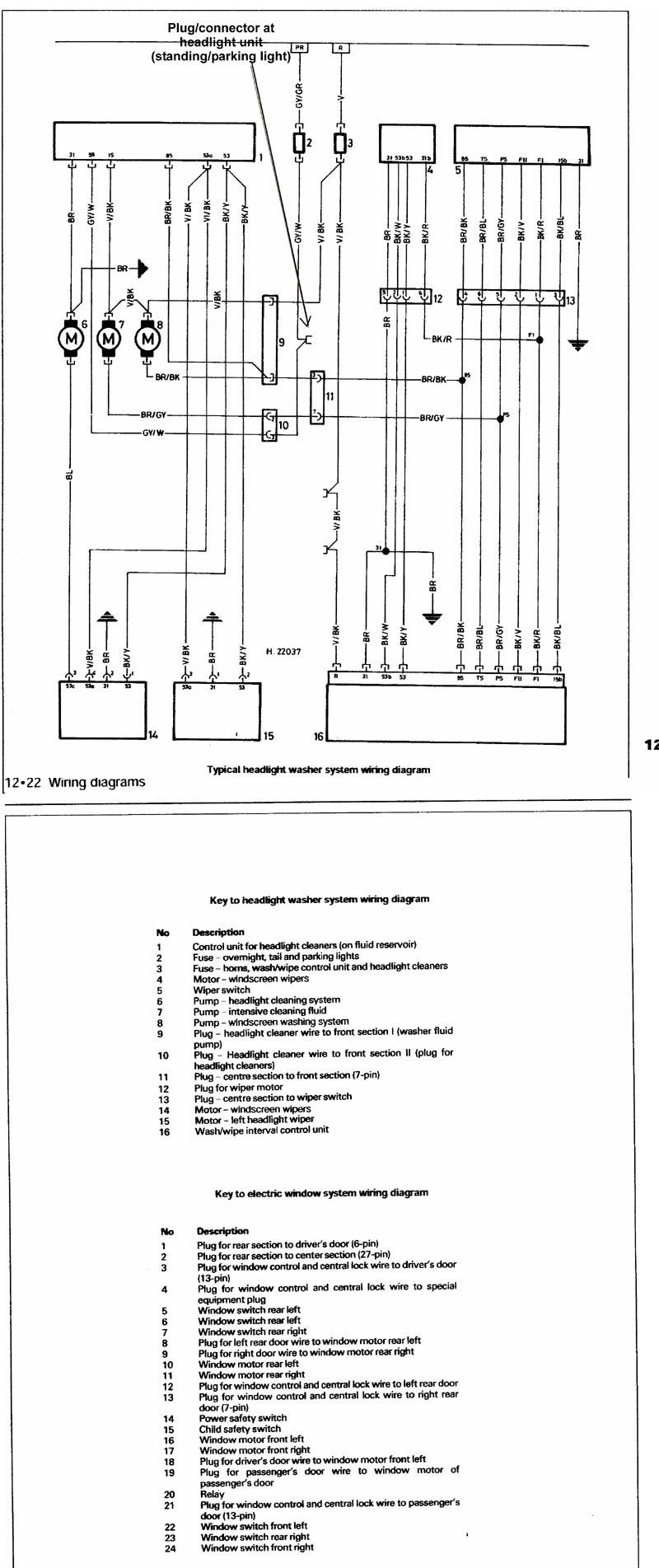